16
Front Panel Description
See Figure 1 on the previous page
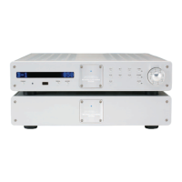
The Evolution 202 Preamplifier is comprised of two chassis: the preamplifier
chassis and the power supply chassis. Front panel functions are described
below:
Chassis
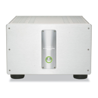
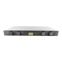
Preamplifier Chassis
The preamplifier front panel provides power on, input and zone selection, level
control, menu functions, and status display.
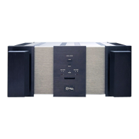
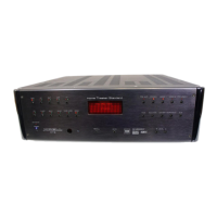
Power Supply Chassis
Powerful transformers, high quality regulators, and extensive electrical and
magnetic shielding are housed in a separate power supply.
Power
1 Power Button or Key
Use this button or key to switch the Evolution 202 between the stand-by and
operational modes.
7 Stand-by/Power LED
The preamplifier and power supply LEDs illuminate red (stand-by) when the
Evolution 202 is plugged into a standar
d AC wall receptacle. They illuminate
blue (operational mode) when the power button (1) is pressed while the
Evolution 202 is in stand-by mode.
Remote Functions on the Front Panel
2 Infrared Emitter
The stand-by/Power LED (7) flashes when the Evolution 202 sends signals via
this infrar
ed emitter to a pr
ogrammable r
emote control, such as the Universal
Krell Touch Screen Remote.
See IR Out Control, on page 36.
4 Infrared Sensor
The infrar
ed sensor r
eceives commands fr
om the Evolution 202 r
emote control.
For proper remote control operation, make sure the infrared sensor is not cov-
ered or obstructed.
(
SECTION FOUR: Anatomy of an Evolution 202 continued)