Status September 2018 Page 3 © Krick Modelltechnik, Knittlingen, Germany
The construction of the model
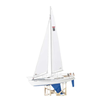
Stage 0, the boat stand, parts 0.1 - 0.3
Fig. individual parts of the stand
Glue the boat stand together from parts 0.1 to
0.3. Grind all edges with sandpaper so that the
burn-off residue is removed from the laser
cutting.
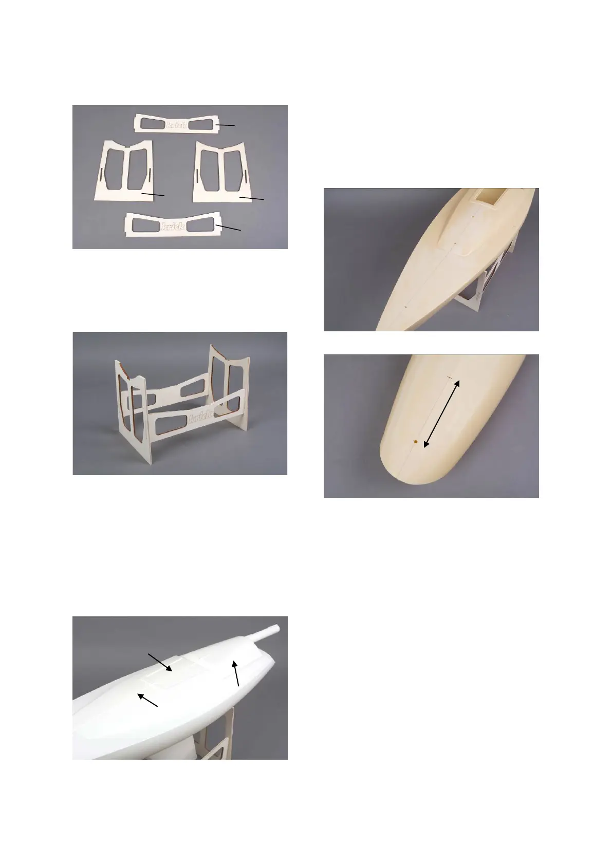
Fig. stand glued together
Stage 1, preparations for hull, parts 1.1 to
1.9
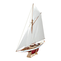
Grind off the surrounding seam on the hull.
Cut out the dome at the rear. Mark the opening
for the sliding hatch as seen from above and
cut it out by scribing several times.
Dome and sliding hatch are shown in drawing
1 A with grid pattern.
Fig. hull processing
The following holes must be drilled in the hull:
3 mm for eye bolts 1.6 and 1.14 for jib suspen-
sion and shrouds.
5 mm for the rudder bearing
6 mm for the mast bearing
Optional: 6 mm for the sterntube if the drive set
is to be installed. See also section X Installa-
tion of the propulsion unit.
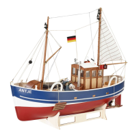
Fig. holes in deck
Fig. holes on underside of hull
Drill the holes exactly according to drawings
1A and 1B.
When drilling the holes, drill very accurately to
avoid large gaps, especially with the rudder
bearing D 5 mm. The tube should fit very
tightly so that it can be easily aligned and re-
mains in position until the adhesive has hard-
ened.
Optional:
If the propulsion set is to be installed, drill the
hole for the stern tube D 6 mm at a distance of
125 mm from the rudder tube.
Make the front reinforcement and attachment
for the jib mount from parts 1.2 to 1.5.
Prime all wooden parts with pore filler before
gluing them into the hull.
Opening for
Sliding Hatch