7
UK
A correct fit of the unit and ingress resistance of the connection are only ensured
using Krohne adapters.
6 Electrical connection
The unit must be connected by a qualified electrician.
Voltage supply according to EN 50178, SELV, PELV.
► Disconnect power.
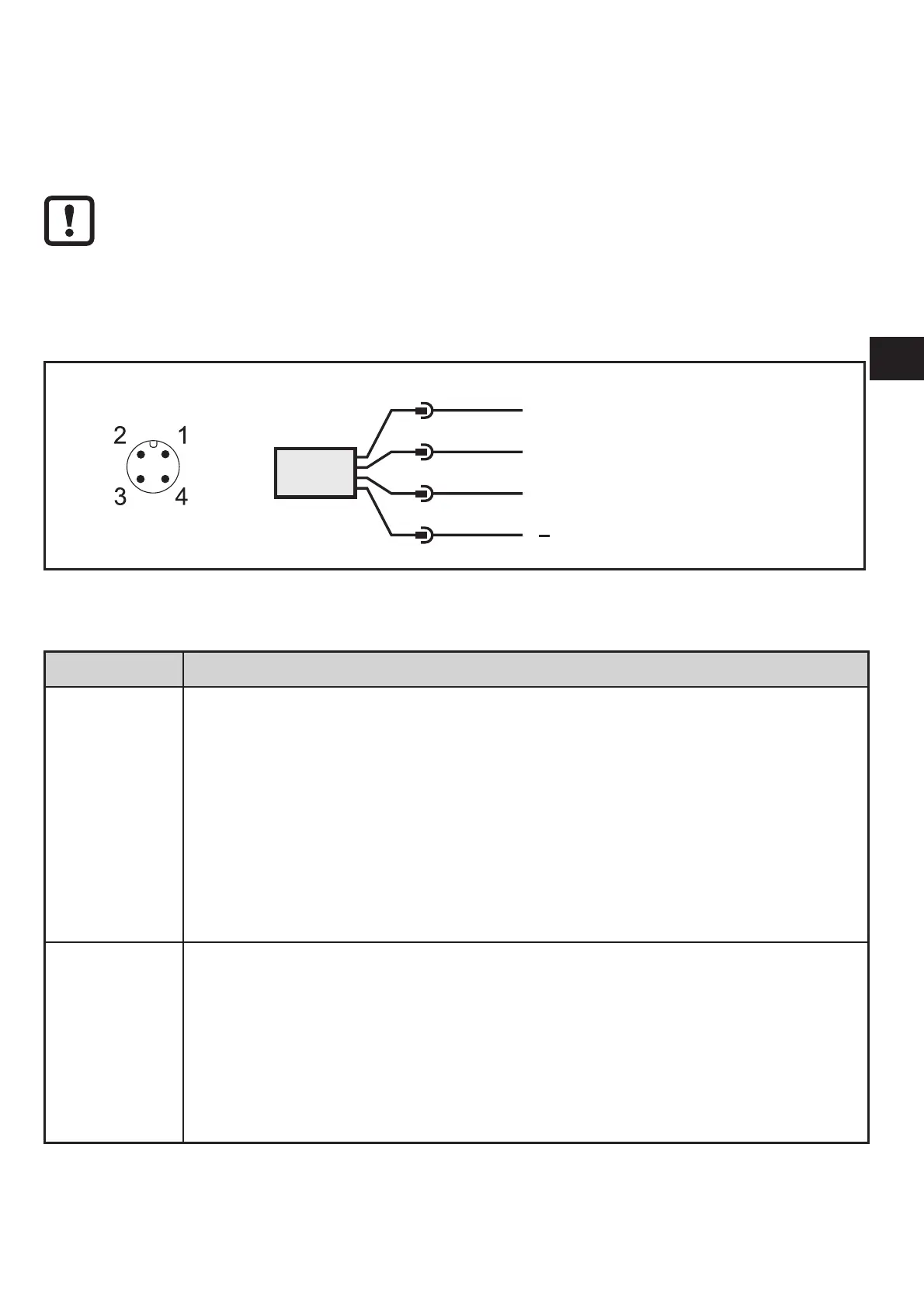
► Connect the unit as follows:
BN
WH
BK
BU
4
1
3
2
OUT2
L
+
L
OUT1
Colours to DIN EN 60947-5-2
BK: black; BN: brown; BU: blue; WH: white
Pin Connection
4
(OUT1)
• switching signal for volumetric flow
• switching signal for temperature
• switching signal for volumetric flow direction
• switching signal for preset counter
• pulse signal for quantity meter
• frequency signal for volumetric flow
• frequency signal for temperature
• IO-Link
• OFF
2
(OUT2/InD)
• switching signal for volumetric flow
• switching signal for temperature
• switching signal for volumetric flow direction
• analogue signal for volumetric flow
• analogue signal for temperature
• input for external meter reset signal (InD)
• OFF