KRONE ISOBUS terminal (CCI200, DELTA terminal) 3
Design of display 3.4
Comprima F 125 - 1, Comprima F 125 XC - 1, Comprima F 155 - 1, Comprima F 155 XC - 1, Comprima V 150 - 1,
Comprima V 150 XC - 1, Comprima V 180 - 1, Comprima V 180 XC - 1, Comprima V 210 XC - 1
Comfort 1.0_en
17
INFORMATION
When switching the terminal on for the first time, the configuration of the machine is loaded
into the terminal and stored in the memory of the terminal. The loading process may take a
few minutes.
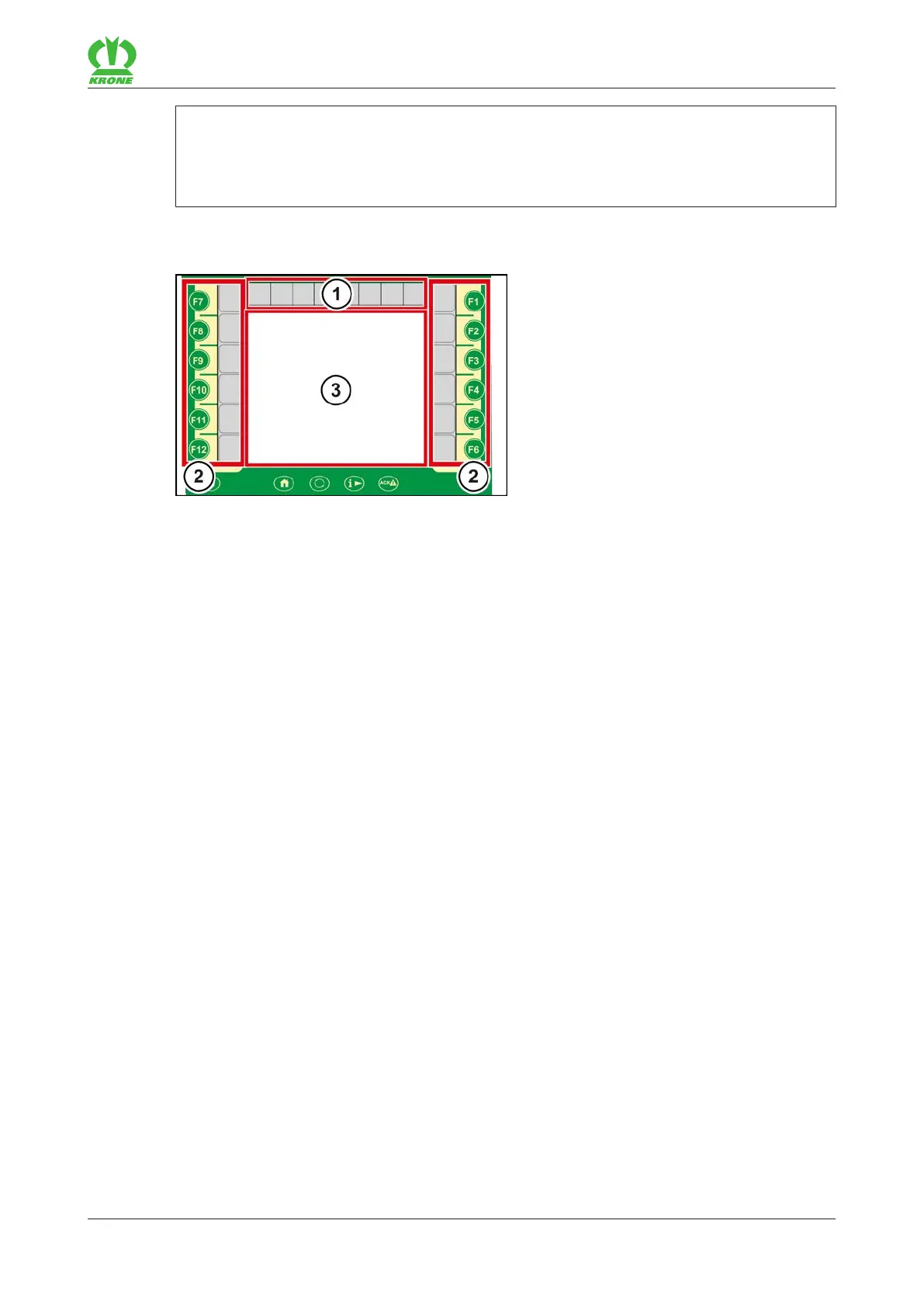
3.4 Design of display
EQG000-033
The display of the terminal is divided into the following areas:
Status line (1)
The status line (1) indicates current states of the machine (depending on how it is equipped),
refer to page23.
Keys (2)
The machine is operated by actuating the keys (F1 to F12) or by pressing the adjacent icons,
refer to page24.
Main window (3)
Values (figures) shown in blue in the main window can be selected using the touch function.
There are the following main window views:
• Road travel screen
• Working screen/s, refer to page28
• Menu level, refer to page34