6 Installation at Site
36 of 60
6 Installation at Site
6.1 General information/Safety regulations
The consultant, construction company or operator are responsible for positioning
and installing the valves. Planning errors and installation errors may impair the
reliable function of the valves and pose a substantial safety hazard.
6.2 Installation
CAUTION
Welding in close proximity to soft-seated valves
Damage to the seat/disc interface!
▷ Ensure that the valve is not heated beyond the temperature limits specified in
the type series booklet.
Only use fasteners (e.g. to DINEN1515-4) and flange gaskets (e.g. to DINEN1514)
made of materials approved for the respective valve size. Always use all flange bolt
holes provided when connecting the valve to the pipe. Refer to the type series
booklet for details on flange connections.
NOTE
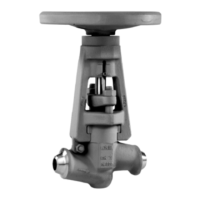
Exception: DN 65 PN 16
When using steel flanges to DINEN1092-1 in conjunction with cast iron valves with
flanges machined to DINEN1092-2, ensure that for nominal size DN65 classed
PN16 the mating flanges are fitted offset by 22.5°.
Table29: Valve bolting DN65 PN16
DN65 PN10/16 (steel/steel):
DINEN1092-1 with DINEN1092-1:
bolts through 8holes
DN65 PN10/16 (steel/cast iron):
DINEN1092-1 with DINEN1092-2: bolt
hole circle to DINEN1092-1 rotated by
22.5°, bolts through 4holes, 4holes
free
NOTE
For the valves to reach the documented Kv values, the flow direction must
correspond to the flow direction arrow.
NOTE
An alternating direction of flow is permitted unless restrictions apply to specific
products.
6.3 Insulation
For handling hot fluids, the valve should be insulated in accordance with the German
energy-saving regulations.