6 Installation at Site
38 of 60
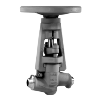
6.5 Bellows-type Globe Valves to DIN/EN
6.5.1 BOA-H
CAUTION
Installation of the valve with the stem pointing downwards
Dirt collecting between the folds of the bellows!
Damage to the bellows!
Valve blockage!
▷ Install the valve with the stem pointing upwards or to the side.
WARNING
Installation of the valve with the stem pointing downwards in steam applications
Damage to the valve through steam hammer!
▷ Install the valve with the stem pointing upwards or to the side.
To avoid warping of the valve during or following installation, open the valve by
approximately two handwheel turns in anti-clockwise direction.
If the following differential pressures are exceeded from DN200 upwards, a balanced
plug design is required.
Table30: Differential pressures in bar
DN 150 200 250 300/350
PN 16 Δp bar - 12 9 6
PN 25 21
30)
The balanced plug only takes effect if the pressure to be sealed lies above the valve
disc. For this reason, flow through valves with balanced plugs must be in the
direction of the arrow on the valve body. An alternating direction of flow is not
permitted.
6.6 Lift Check Valves to DIN/EN
6.6.1 BOA-R
A minimum pressure is required for opening. If this minimum pressure is not reached,
the spring can be dismantled.
Table31: Minimum opening pressures in mbar
DN 15-50 65-150 200-350
With spring 250 200 150
Without spring 25 16 22
NOTE
Flow through lift check valves must be in the direction of the arrow on the valve
body. When equipped with a spring (950), they can be used in vertical pipes with
upward or downward flow. Valves without spring can only be installed in a
horizontal position, i.e. in horizontal pipes and with the body cover (161) pointing
upwards.
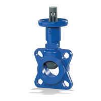
6.6.2 BOA-RVK
The valve is clamped between the two mating flanges of the pipeline and centred by
the flange bolting.
30) No balanced plug available.