7 Operation
50 of 68
Calio
1157.821/04-EN
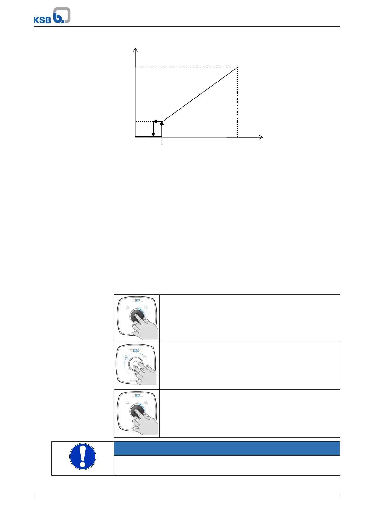
100%
2 V
%
0%
10 V1,5 V
U [V DC]
Fig.28: Analog 0-10V signal as setpoint input for the pump set
Use the KSB ServiceTool for setting the limits and parameters for the following
functions:
▪ Starting up the pump
▪ Stopping the pump
▪ Monitoring for broken wires
▪ Pump set behaviour in the event of a broken wire
The analog input can also be configured as an input for actual values (differential
pressure, fluid temperature). The settings for the analog input are described in the
KSB ServiceTool supplementary operating manual.
Setting
Press the control element to activate the display from idle mode. The display will
show the current operating mode as well as, in alternation, the electrical input
power and the flow rate. If 5minutes pass without any settings being made or the
control button being pressed, the display will revert to idle mode.
Table23: Starting and stopping 0-10V
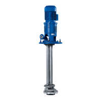
Step 1: Enabling the sub-mode (DUAL, Modbus, 0-10V)
▪ Press the control element for 6seconds.
– One of the symbols representing the Dual-pump Operation
(DUAL), Modbus and 0-10V sub-modes will start flashing.
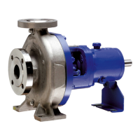
Step 2: Selecting the 0-10V operating mode
▪ Turn the control element and select the required operating
mode.
0-10V
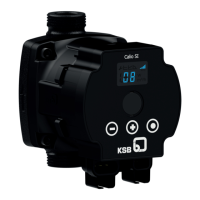
Step 3: Activating or de-activating the 0-10V operating mode
▪ Press the control element.
– The symbol will light up. When the signal is activated, the
circular segments will indicate the value of the input signal.
NOTE
If 10seconds pass without any settings being made or saved, the control unit will
revert to the previous settings.