Size Suction nozzle Discharge nozzle
DN F
x
[N]
F
y
[N]
F
z
[N]
∑F
[N]
M
x
[Nm]
M
y
[Nm]
M
z
[Nm]
DN F
x
[N]
F
y
[N]
F
z
[N]
∑F
[N]
M
x
[Nm]
M
y
[Nm]
M
z
[Nm]
125-100-400 125 1400 1250 1120 2186 740 530 670 100 1050 950 1180 1843 620 440 510
150-125-200 150 1750 1600 1400 2754 880 610 720 125 1250 1120 1400 2186 740 530 670
150-125-250 150 1750 1600 1400 2754 880 610 720 125 1250 1120 1400 2186 740 530 670
150-125-315 150 1750 1600 1400 2754 880 610 720 125 1250 1120 1400 2186 740 530 670
150-125-400 150 1750 1600 1400 2754 880 610 720 125 1250 1120 1400 2186 740 530 670
200-150-200 200 2350 2100 1900 3680 1150 800 930 150 1600 1400 1750 2754 880 610 720
200-150-250 200 2350 2100 1900 3680 1150 800 930 150 1600 1400 1750 2754 880 610 720
200-150-315 200 2350 2100 1900 3680 1150 800 930 150 1600 1400 1750 2754 880 610 720
200-150-400 200 2350 2100 1900 3680 1150 800 930 150 1600 1400 1750 2754 880 610 720
200-150-500 200 2350 2100 1900 3680 1150 800 930 150 1600 1400 1750 2754 880 610 720
200-200-250 200 2350 2100 1900 3680 1150 800 930 200 2100 1900 2350 3680 1150 800 930
250-200-315 250 3340 2980 2700 5227 1780 1260 1460 200 2100 1900 2350 3680 1150 800 930
250-200-400 250 3340 2890 2700 5227 1780 1260 1460 200 2100 1900 2350 3680 1150 800 930
250-200-500 250 3340 2890 2700 5227 1780 1260 1460 200 2100 1900 2350 3680 1150 800 930
300-250-315 300 4000 3580 3220 6260 2420 1720 1980 250 2980 2700 3340 5227 1780 1260 1460
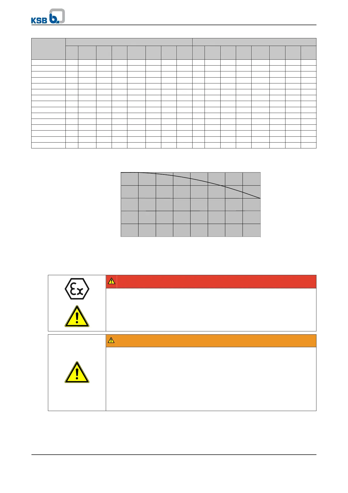
Correction coefficients depending on material and temperature (see diagram below).
0,9
0,92
0,94
0,96
0,98
1
0
20 40 60 80 100 120 140
160
°C
Correction coefficient
Fig. 12:
Temperature correction diagram for "G" variant (JL1040/ A48CL35B)
5.4.3
Auxiliary connections
DANGER
Risk of potentially explosive atmosphere by mixing of incompatible fluids in the
auxiliary piping
Risk of burns!
Explosion hazard!
▷ Make sure that the barrier fluid and quench liquid are compatible with the
fluid pumped.
WARNING
Failure to use or incorrect use of auxiliary connections (e.g. barrier fluid, flushing
liquid, etc.)
Risk of injury from escaping fluid!
Risk of burns!
Malfunction of the pump!
▷ Refer to the general arrangement drawing, the piping layout and pump
markings (if any) for the quantity, dimensions and locations of auxiliary
connections.
▷ Use the auxiliary connections provided.
5 Installation at Site
26 of 74
MegaCPK

 Loading...