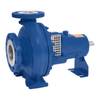
Fig. 16: Bearing bracket with constant level oiler
1
Constant level oiler 2 Vent plug
3 Connection elbow of the constant
level oiler
4 Screw plug
5 Bearing bracket
1. Pull out the vent plug (2).
2. Hinge down the reservoir of the constant level oiler (1) from the bearing
bracket (5) and hold it in this position.
3. Fill in oil through the hole for the vent plug until the oil reaches the connection
elbow of the constant level oiler (3).
4. Completely fill the reservoir of the constant level oiler (1).
5. Snap the constant level oiler (1) back into its operating position.
6. Fit the vent plug (2) again.
7. After approximately 5 minutes, check the oil level in the glass reservoir of the
constant level oiler (1).
The oil reservoir must be properly filled at all times to provide a constant oil
level. Repeat steps 1 - 6, if necessary.
8. To check the function of the constant level oiler (1), slowly drain some oil via
the screw plug (4) until air bubbles can be seen in the oil reservoir.
NOTE
An excessively high oil level can lead to a temperature rise and to leakage of the
fluid handled or oil.
6.1.3 Shaft seal
Shaft seals are fitted prior to delivery.
Observe the instructions on dismantling (⇨ Section 7.4.6 Page 50) or assembly
(⇨ Section 7.5.3 Page 55) .
If applicable, fill the reservoir of non-pressurised external fluid in accordance with
the general arrangement drawing.
Prior to starting up the pump, apply barrier pressure as specified in the general
arrangement drawing.
Apply the quantities and pressures specified in the data sheet and the general
arrangement drawing.
Reservoir of non-
pressurised external fluid
Double mechanical seal
External liquid feed
6 Commissioning/Start-up/Shutdown
34 of 74
MegaCPK

 Loading...