RDL
11
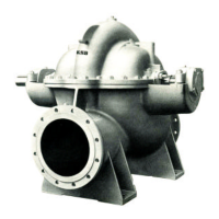
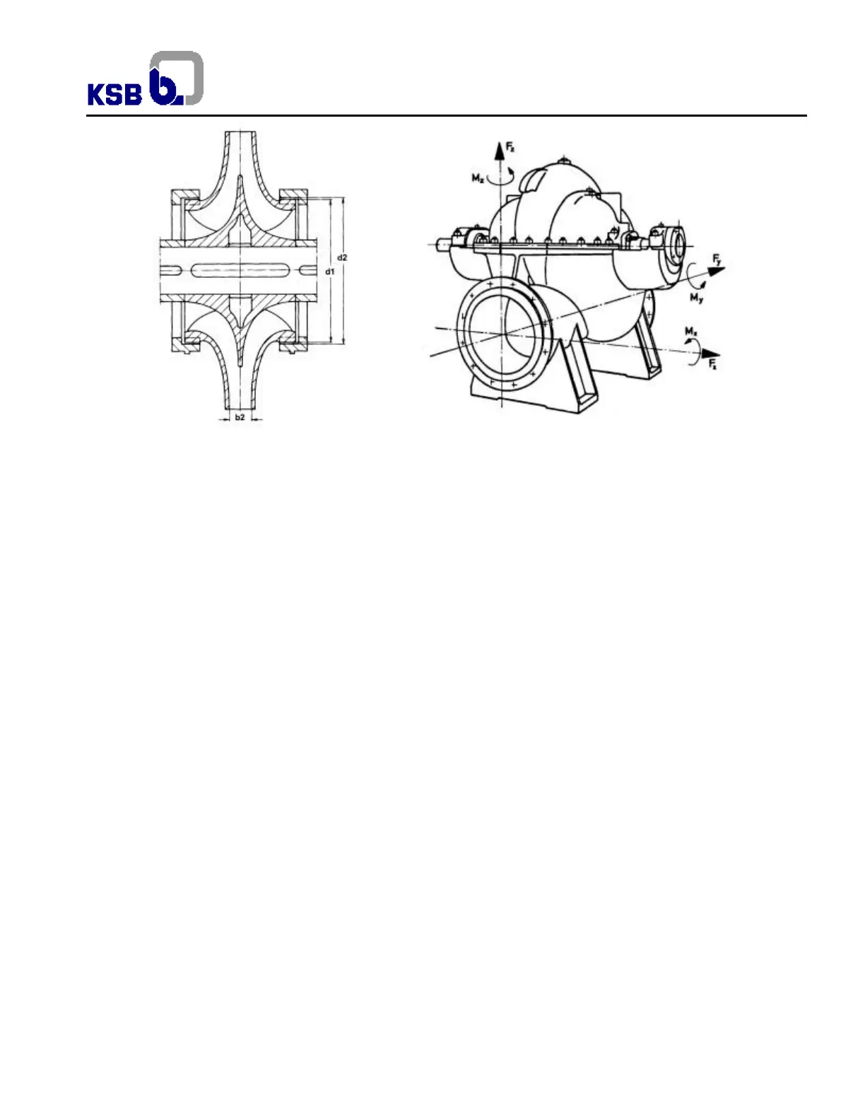
Fig.4 – Sealing clearance and impeller diameter Fig.5 – Permissible forces and moments on the flanges (see table 1)
4.4 Design details
4.4.1 Casing
Horizontal, axially split volute casing, with upper and lower casing. Horizontal and opposite suction and discharge nozzle, in the
lower casing. The surfaces between the casings are properly machined and the sealing is done with seal bandage of silicone
(598 HB Loctite). This design allows disassembly of the impeller, shaft and sleeves without disassembly of the piping. The
protection of pump casing against wear caused by impeller rotation is made through replaceable wear rings fixed in machined
channels in the lower casing. This system prevents rotation and axial displacement of wear rings.
4.4.2 Impeller
Impeller is radial, double suction, with vanes of wide curvature, fixed on the shaft by means of two symmetric parts set (space
sleeve, shaft protecting sleeve and shaft nut). Shaft nuts are out of flow area and are locked to the shaft by means of threaded
screw and pins. From size 600-540 inclusive the impeller is produced with replaceable wear rings. In special execution up to
size 500-890 inclusive impeller wear rings can also be provided. Usually two different standard and interchangeable hydraulics
(A and B), are available for each pump size. Axial thrust is hydraulically compensated.
4.4.2.1 Peripheral Speed
When determining pump rotation, always check if impeller material is appropriate for the peripheral speed. (Fig.6).
4.4.3 Shaft
Pump shaft is supported between bearings. Bearing casings are fixed to their brackets to facilitate the disassembly of rotor
together with the bearing. Up to size 500-890 the bearing casing is part integrated to the lower casing. For bigger sizes bearing
brackets are fixed to the lower casing through studs and nuts. Bearings are protected by sealing rings on shaft against drop
from the stuffing box. Pumps up to DN 300 have ball bearings in both sides. For bigger sizes, bearings have cylindrical roller
bearing at the drive end, and a deep groove ball bearing at the N.D.E.
4.4.4 Shaft Sealing
Pump is shaft sealed by gland packing (standard) or optionally by mechanical seal. In the sealing area, the shaft is provided
with easily replaceable protective sleeves.
Usually gland packing is lubricated by pumped liquid, except on applications which the fluid is inadequate for these functions. In
these cases, use an external source with clean liquid, with a pressure of 1,5 to 3,0 bar (20 to 40 psi) over the suction pressure.
The volume of lubrication / sealing liquid of external source is obtained through the diagram according to fig. 7, and for wash
use the same pressure and flow 10 times higher than that used for lubricating / sealing.
Pressure and flow refer to values for each chamber.