36
WARNING!
Wait for about 5 minutes for the internal D.C. bus bar capacitors to be
completely discharged
.
4.2.6 Startup procedure for parallel system
Connect parallel cable, input/output cable, and battery cable well; modify the parallel
board jumpers correctly.
Measure the positive and negative battery pack voltage. Battery switch is opened
temporarily.
Switch ON the output switch at the front door.
According to the startup procedure for single unit, set the operation mode of each
UPS: single mode is changed to parallel mode; set the parallel number for each
UPS; up to 4 units can be parallel; set the ID of each cabinet, the ID of each unit
must be different.
Switch ON the input switch. Close the external input switch and start from mains.
After start from mains, check the LCD interface of each UPS to see if the ID, VA is
the same with the actual values.
Switch ON the external battery switch of each UPS. Check if the charging current
displayed in LCD is normal.
Note!
The UPS cannot be parallel until each single unit is normal.
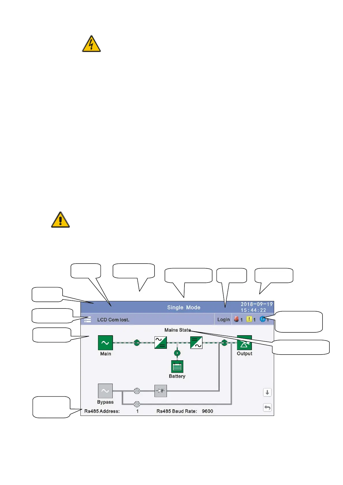
4.3 The Display
4.3.1 Datas: Displays the flow state of UPS work, and quickly enters real-time data by
Power rate
150kVA
50kVA
Setting mode Date/time
Current fault
and event
log in
Logo
Home
Operation staus
Data
Comm.
setting
Alarm
 Loading...