2 SETUP
4
F02149-01
– Roll down the film at the sides.
Guideline
To avoid damaging the vehicle while setting it up, do
not remove the protective film on each component until
installing the component, and leave it on the vehicle until
work has been completed.
– Remove the separate enclosure and unpack it. Check that the
scope of supply is complete using the enclosed packing list.
Info
The procedure for missing components is described in
the Customer Service Manual.
– Check the vehicle for transport damage.
Info
The procedure in the event of transport damage is
described in the Customer Service Manual.
F02128-10
– Remove cable ties and protective film on the handlebar.
Warning
Danger of accidents A repaired handlebar poses a
safety risk.
If the handlebar is bent or straightened, the mate-
rial becomes fatigued. The handlebar may break as a
result.
– Change the handlebar if the handlebar is damaged
or bent.
– Position the handlebar.
Info
Make sure the cables and wiring are positioned cor-
rectly.
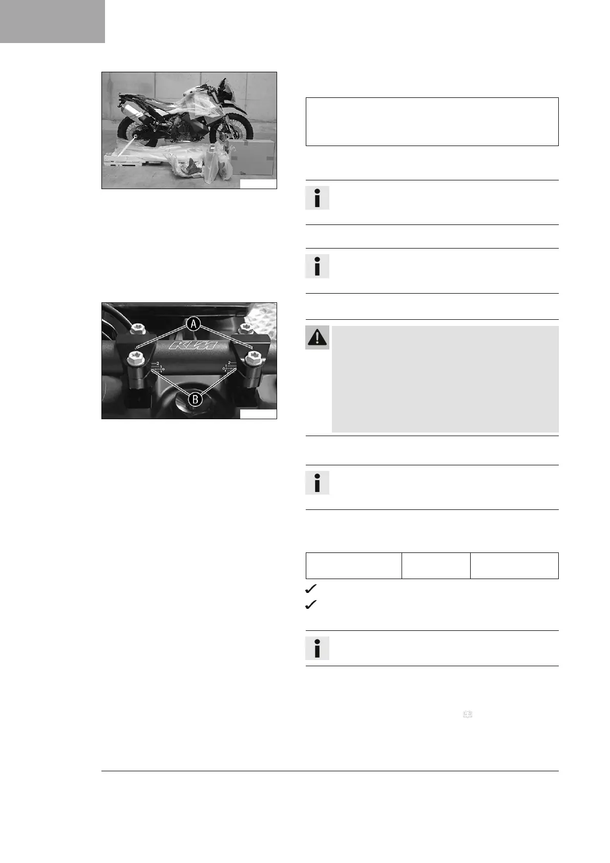
– Position the handlebar clamps. Mount and tighten the screws
evenly.
Guideline
Screw, handlebar
clamp
M8 20 Nm (14.8 lbf ft)
Markings
A
face the rear.
Handlebar scale markings
B
are located centrally
between the handlebar clamps.
Info
Keep the installed gap widths equal when tightening.
– Check the handlebar position.
» If the handlebar position is not adjusted as required by the
customer:
– Adjust the handlebar position. ( p. 9)

 Loading...