S.1
ENGINE
BODY
68
mm
STROKE
SERIES
WSM,
01
164
A19SFOO2
Checking Valve Clearance
IMPORTANT
when engine
is
cold.
0
Valve
clearance must be checked and adjusted
1.
Remove the head cover.
2.
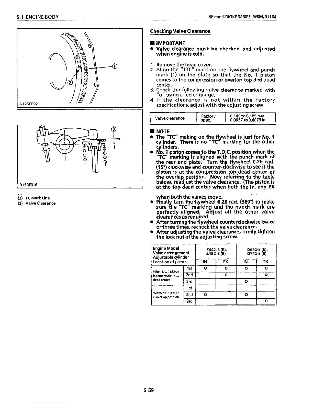
Align the
"ITC"
mark on the flywheel and punch
mark
(1)
on
the plate
so
that the
No.
1
piston
comes to the compression or overlap top ded dead
center.
3.
Check the following
valve
clearance marked with
''0''
using
a
feeler gauge.
4.
If
the clearance
is
not within the factory
specifications, adjust with the adjusting screw.
I
I
Factory
I
0.145to0.185
mm
spec.
0.0057
to
0.0073
in.
I
Valve clearance
NOTE
0
The
"TC"
making on the flywheel
is
just for No.
1
cylinder. There
IS
no "TC' marking for the other
cylinders.
0
No.
1
piston comes
.to
the T.D.C. osition when the
the rear end plate. Turn
the
flywheel 0.26 rad.
(15')
clockwise and counter-clockwise
to
see
if
the
piston
is
at the compression top dead center
or
the overlap position. Now referring to the table
below, read'ust the valve clearance. (The piston
is
at the top dead center when both the In. and
EX
(2)
TCMark Line
when both the valves move.
(3)
Valve Clearance
0
Finally turn the flywheel
6.28
rad.
(360')
to make
sure the
"TC"
marking and the punch mark are
perfectly aligned. Adjust
all
the other valve
clearances
as
required.
0
After turning the flywheel counterclockwise
twice
or three times, recheck the valve clearance.
0
After adjusting
the
valve
clearance,
firmly tighten
the lock nut
of
the adjusting screw.
"TC"
marking
is
aligned with
t
R
e
punch mark of
0
1
58F016
ve
arrengemen
Is
compresslon
top
s-59