S.1
ENGINE
BODY
68mmSTROKESERlES WSM,O1165
Factory
spec.
Valve clearance
AI
16F016
0.145 to 0.1 85
mm
0.0057
to
0.0073 in.
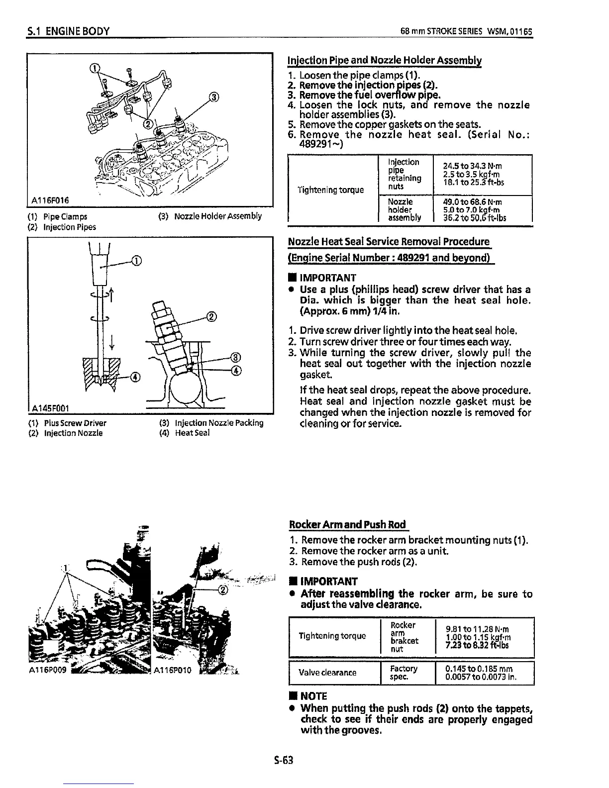
(1) Pipeclamps (3) Nozzle Holder Assembly
(2) Injection Pipes
I
A145F001
(1)
Plusscrew Driver (3) injection Nozzle Packing
(2) Injection Nozzle
(4)
HeatSeal
Injection Pipe and Nozzle Holder Assembly
1.
Loosen the pipe clamps
(1).
2.
Remove the injection ipes
(2).
4.
Loosen
the
lock nuts, and remove the nozzle
holder assemblies
(3).
5.
Remove the copper gaskets on the seats.
6.
Remove the nozzle heat seal. (Serial
No.:
48929
1
-)
3.
Remove
the
fuel over
P
low pipe.
Tightening torque
Nozzle
holder
Nozzle Heat Seal Service Removal Procedure
(Engine Serial Number
:
489291
and beyond)
IMPORTANT
0
Use a plus (Phillips head) screw driver that has
a
Dia. which
is
bigger than the heat seal hole.
(Approx.
6
mm)
114
in.
1.
Drive screw driver lightly into the heat seal hole.
2.
Turn screw driver three or four times each way.
3.
While turning the screw driver, slowly pull the
heat seal out together
with
the injection nozzle
gasket.
If
the heat seal drops, repeat the above procedure.
Heat
seal
and injection nozzle gasket must be
changed when the injection nozzle
is
removed for
cleaning or for service.
Rocker Arm and Push Rod
1.
Remove the rocker arm bracket mounting nuts
(1).
2.
Remove the rocker arm as a unit.
3.
Remove the push rods
(2).
0
After reassembling the rocker arm, be sure to
IMPORTANT
adjust the valve clearance.
:1:
cz?
9.81 to 1 1.28
Nsm
Rocker
Tightening torque
I
Hgcet
I
1
.OO
to 1
.I
5
kgfem
7.23 to 8.32 ft-lbs
NOTE
When putting the push rods
(2)
onto the tappets,
check to see
if
their
ends are properly engaged
with
the grooves.
S-63