S.l
ENGINE
BODY
68
mm
STROKE
SERIES
WSM,
01
160
I
B088F046
'0
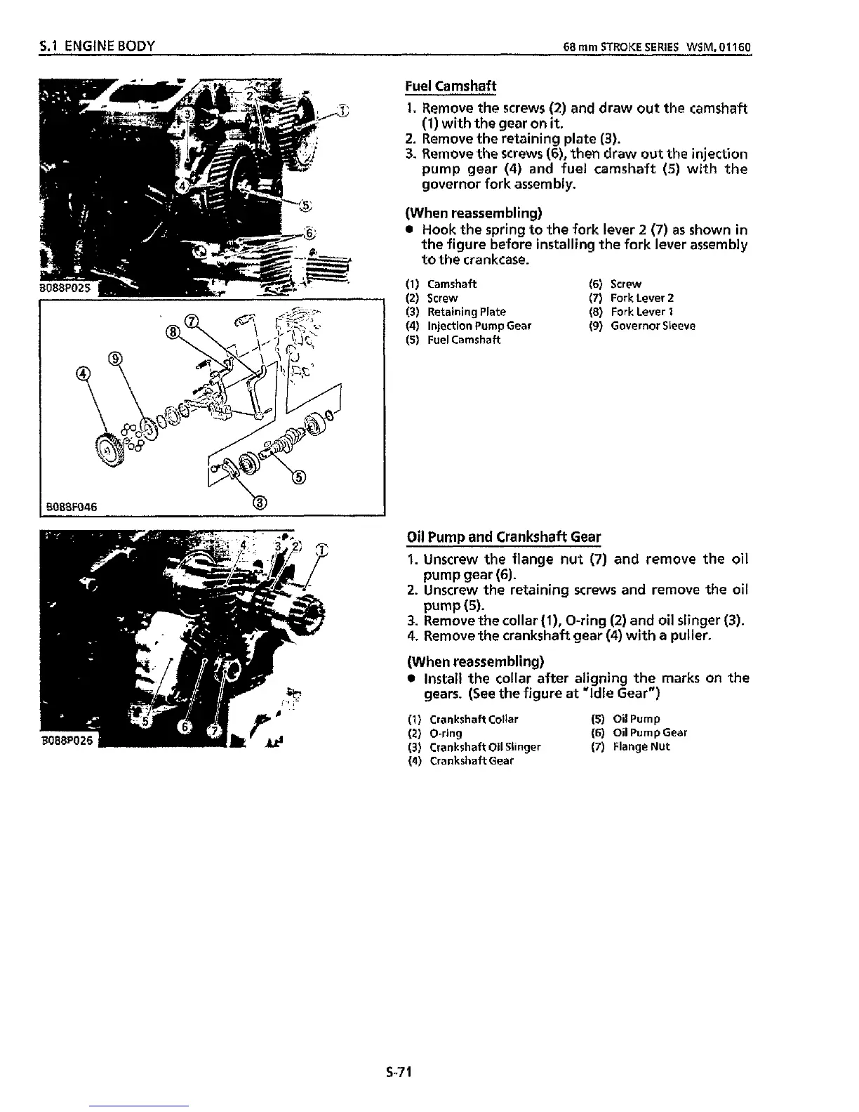
Fuel Camshaf?
1.
Remove
the
screws
(2)
and draw out the camshaft
(1)
with the gear on
it.
2.
Remove the retaining plate
(3).
3.
Remove
the
screws
(6),
then draw out the injection
pump gear
(4)
and fuel camshaft
(5)
with
the
governor fork assembly.
(When reassembling)
Hook
the
spring to the fork lever
2
(7)
as
shown in
the figure before installing the fork lever assembly
to
the crankcase.
(1)
Camshaft
(6)
Screw
(2)
Screw
(7)
Fork Lever
2
(3)
Retaining Plate
(8)
Fork Lever
1
(4)
Injection Pump Gear
(9)
Governor Sleeve
(5)
Fuel Camshaft
Oil
Pump
and Crankshaft Gear
1.
Unscrew the flange nut
(7)
and remove
the
oil
2.
Unscrew
the
retaining screws and remove the
oil
3.
Remove the collar
(l),
O-ring
(2)
and oil slinger
(3).
4.
Remove the crankshaft gear
(4)
with
a
puller.
(When reassembling)
Install the collar after aligning the marks on the
gears. (See
the
figure
at
"Idle Gear")
(1)
Crankshaft Collar
(5)
Oil
Pump
(2)
O-ring
(3)
Crankshaft
Oil
Slinger
(7)
Flange Nut
(4)
Crankshaft Gear
pump gear
(6).
pump(5).
(6)
Oil
Pump Gear
5-7
1