S.1
ENGINE
BODY
68 mm STROKE
SERIES
WSM,
01
160
Valve guide
I.D.
(Intake and exhaust)
I
(When
removing)
(When
installing)
Factory 6.010 to 6.025
mm
spec. 0.23661 to0.23721
in.
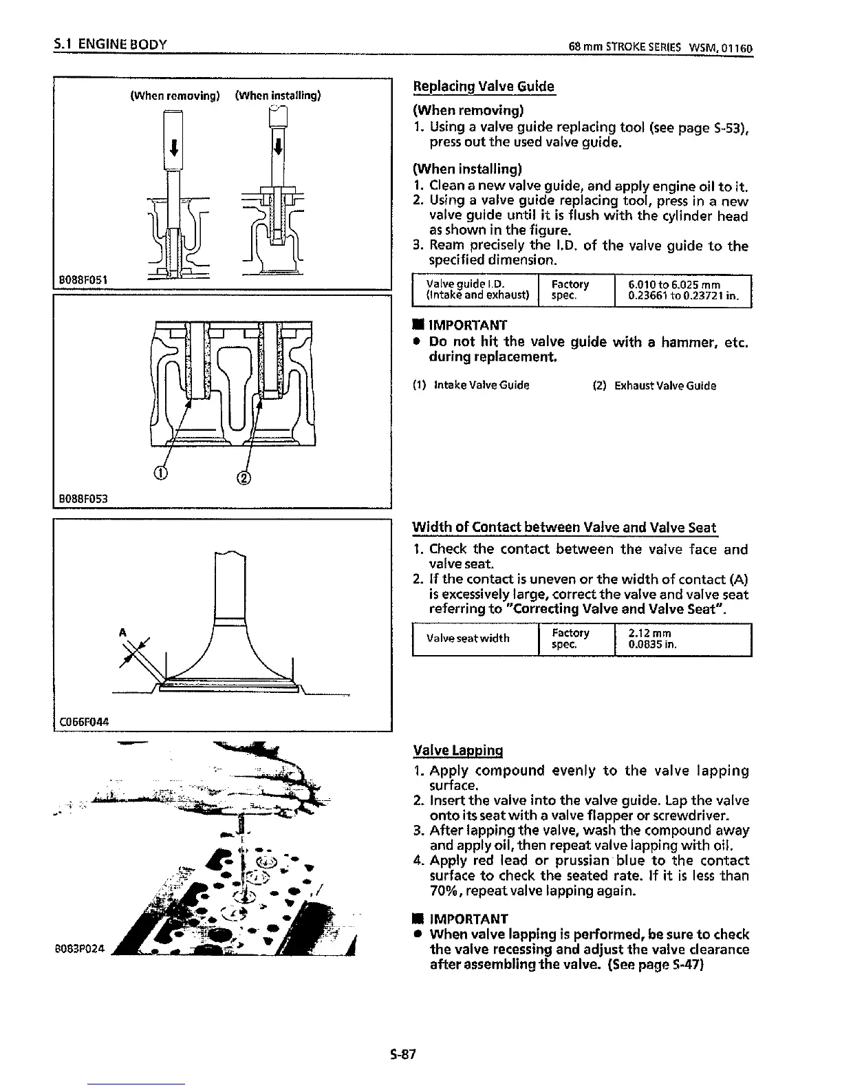
Replacing Valve Guide
(When removing)
1.
Using a valve guide replacing tool (see page
5-53),
(When installing)
1.
Clean a new valve guide, and apply engine
oil
to
it.
2.
Using a valve guide replacing tool, press
in
a new
valve guide
until
it
is
flush
with
the cylinder head
as
shown
in
the figure.
3.
Ream precisely the
I.D.
of the valve guide
to
the
specified dimension.
press
out
the used valve guide.
Width
of
Contact between Valve and Valve Seat
1.
Check the contact between the valve face and
valve seat.
2.
If
the contact
is
uneven or the
width
of
contact
(A)
is
excessively large, correct the valve and valve seat
referring
to
"Correcting Valve and Valve Seat".
I
Factory
2.12mm
I
0.0835in.
I
Valveseatwidth
1
spec.
C066F044
I
-
Valve Lapping
1.
Apply compound evenly
to
the valve lapping
surface.
2.
Insert the valve
into
the valve guide.
Lap
the valve
onto
its
seat
with
a valve flapper
or
screwdriver.
3.
After lapping the valve, wash the compound away
and apply
oil,
then repeat valve lapping
with
oil.
4.
Apply red lead
or
Prussian blue to the contact
surface
to
check the seated rate.
If
it
is
less than
70%,
repeat valve lapping again.
IMPORTANT
When valve lapping
is
performed, be sure to check
the valve recessing and adjust the valve clearance
after assembling the valve.
(See
page
$47)
i
--
.-
**
8083P024
A
S-87