5.4
FUELSYSTEM
68
mm
STROKE
SERIES
WSM,
01 161
Pump element fuel
tightness (Fuel pressure)
AI
r
Allowabie
limit
2133 psi
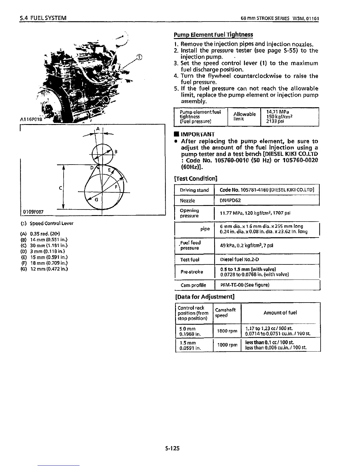
(1)
Speed Control Lever
(A) 0.35 rad. (200)
(6)
14
mm
(0.551
in.)
(C)
30mm(1.181
in.)
(D) 3
mm
(0.1
18 in.)
(E)
15
mm
(0.591 in.)
(F)
18
mm
(0.709 in.)
(G)
12
mm
(0.472
in.)
~
Driving stand
Nozzle DN4PD62
Code
No.
105781-4160 [DIESEL
KIM1
CO.LTD]
I
Pump Element Fuel Tightness
~~~
Cam profile
1.
Remove the injection
pipes
and injection nozzles.
2.
Install the pressure tester (see page
S-55)
to
the
injection pump.
.
3.
Set the speed control lever
(1)
to the maximum
fuel discharge position.
4.
Turn the flywheel counterclockwise
to
raise
the
fuel pressure.
5.
If
the fuel pressure can
not
reach the allowable
limit, replace the pump element or injection pump
assembly.
~
PFM-TE-OO (See figure)
I
5.0
mm
0.1969
in.
IMPORTANT
0
After replacing the pump element, be sure to
adjust
the
amount
of
the fuel injection using a
pump tester and
a
test bench
[DIESEL
KlKl
CO.LTD
:
Code
No.
105760-0010
(50
Ht)
or
105760-0020
(60Hz)I.
[Test Condition]
1
.I7 to 1.23 cc/IOo
st.
'*O0
rpm
0.0714to0.0751 cu.in.ll00st.
Opening
I
pressure
I
11.77 MPa,
120
kgf/crn2, 1707
Psi
I
6
mm dia.
x
I
.6
rnm
dia.
x
255
mm
long
I
0.24
in.
dia. x0.08 in. dia.
x
23.62 in. long
49 kPa,
0.2
kgf/cmz,
7
psi
I
Fuel feed
pressure
I
Test fuel Diesel fuel No.2-D
I
I
0.5 to 1.5
mm
(with valve)
1
I
0.0728 to 0.0768 in. (with valve)
[Data for Adjustment]
Control rack
Camshaft
1-
position (from
I
speed
I
stop position)
Amountoffuel
lessthanO.l cc/100st.
1.5
mm
0.0591 in.
I
"O0
rpm
I
less
than 0.006 cu.in./ 100
st.
5-125