5.5
ELECTRICAL
SYSTEM
68
rnrn
STROKE
SERIES
WSM,
01 160
Clearance
between
armature
shaftand
bushing
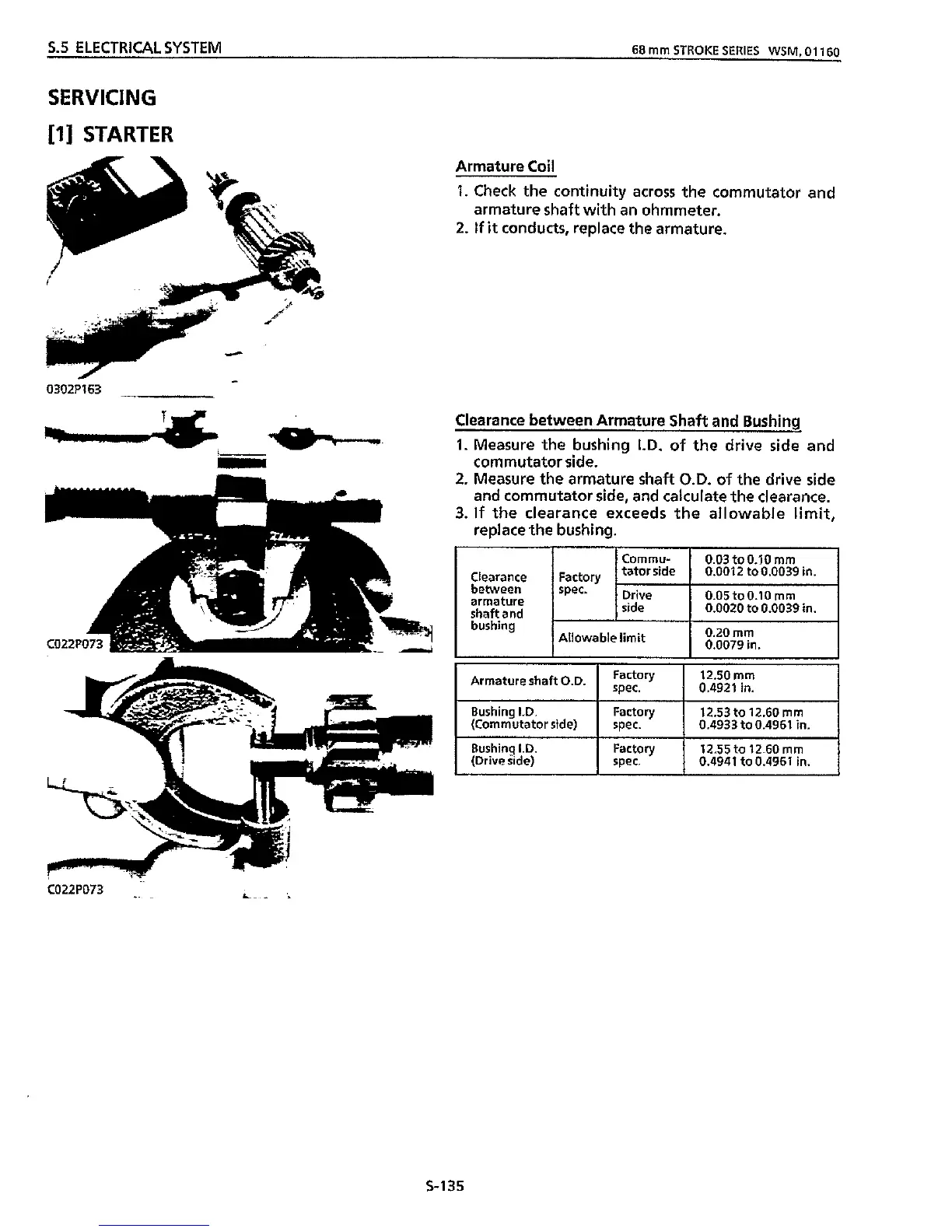
Armature
Coil
1.
Check the continuity across the commutator and
armature shaft with an ohmmeter.
2. If
it
conducts, replace the armature.
Cornmu-
0.03
toO.10
rnrn
tator side
0.0012
to 0.0039 in.
0.05to0.10
mm
side 0.0020 to 0.0039 in.
0.20
mm
0.0079 in.
spec.
Drive
Allowable limit
SERVICING
[I]
STARTER
12.50
mrn
0.4921 in.
Armature shaft O.D.
F:gry
Bushing I.D. Factory 12.53 to 12.60
rnrn
(Commutator side) spec. 0.4933 to 0.4961 in.
Rushinq
I.D.
Factory 12.55 to
12.60
rnrn
(Drive iide) spec. 0.4941 to 0.4961 in.
0302P163
-
Clearance between Armature Shaft
and
Bushing
1.
Measure
the
bushing
I.D.
of the drive side and
commutator side.
i
S-135