M.4
FUEL
SYSTEM
68
mm
STROKE
SERIES
WSM,
01
160
I
3109F032
FUEL
SYSTEM
[I]
GENERAL
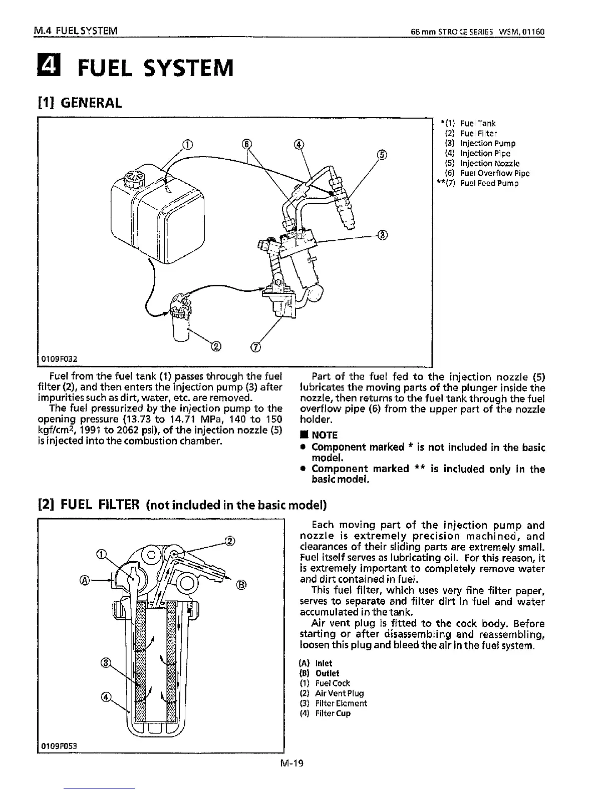
*(I)
Fuel Tank
(2)
Fuel Filter
(3) injection Pump
(4)
Injection Pipe
(5)
Injection Nozzle
(6)
Fuel Overflow Pipe
**(7)
Fuel Feed Pump
Fuel from the fuel tank
(1)
passes through
the
fuel
filter
(Z),
and then enters the injection pump
(3)
after
impurities such as dirt, water, etc. are removed.
The fuel pressurized by the injection pump to the
opening pressure
(13.73
to
14.71
MPa.
140
to
150
holder.
Part
of the fuel fed to the injection nozzle
(5)
lubricates the moving parts of the plunger inside the
nozzle, then returns to the fuel tank through
the
fuel
overflow pipe
(6)
from the upper part of the nozzle
kgfkmz,
1991
to
2062
psi),
of the injection nozzle
(5)
is
injected into the combustion chamber.
I
NOTE
0
Component marked
*
is
not included
in
the basic
model.
basic model.
0
Component marked
**
is
included only
in
the
[2]
FUEL FILTER
(not
included
in
the basic model)
0109F053
M-19
Each
moving part of the injection pump and
nozzle
is
extremely precision machined, and
clearances of their sliding parts are extremely small.
Fuel
itself
serves as lubricating oil. For
this
reason,
it
is
extremely important to completely remove water
and dirt contained in fuel.
This fuel filter, which uses very fine filter paper,
serves to separate and filter dirt
in
fuel and water
accumulated
in
the tank.
Air vent plug
is
fitted to
the
cock body. Before
starting or after disassembling and reassembling,
loosen
this
plug and bleed the air in the fuel system.
(A)
Inlet
(B)
Outlet
(1)
FuelCock
(2) Air Vent Plug
(3) Filter Element
(4)
Filter Cup