M.4
FUEL
SYSTEM
68
mm STROKE SERIES
WSM,
01
160
(1)
Pump
Element
I
1001
1F043
(2)
Delivery Valve
I
001
1
F042
(3)
Dumping
Valve
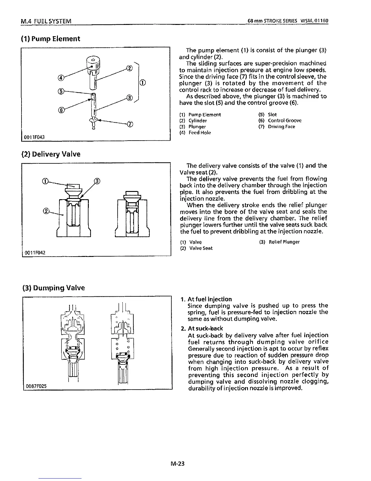
The pump element
(1)
is
consist of
the
plunger (3)
and cylinder
(2).
The
sliding
surfaces are super-precision machined
to maintain injection pressure at engine
low
speeds.
Since the driving face
(7)
fits
in
the control sleeve, the
plunger
(3)
is
rotated by the movement of the
control rack to increase or decrease of fuel delivery.
As
described above, the plunger
(3)
is
machined
to
have the slot
(5)
and the control groove
(6).
(2)
Cylinder
(6)
Control Groove
(3)
Plunger
(7)
Driving
Face
(4)
Feed
Hole
(1)
Pump Element
(5)
Slot
The delivery valve consists of the valve
(1)
and the
Valve seat
(2).
The delivery valve prevents the fuel from flowing
back into the delivery chamber through
the
injection
pipe.
it
also prevents the fuel from dribbling at the
injection nozzle.
When the delivery stroke ends the relief plunger
moves into
the
bore
of
the valve seat and seals the
delivery line from the delivery chamber. The relief
plunger lowers further
until
the valve seats suck back
the fuel to prevent dribbling at the injection nozzle.
(1)
Valve
(3)
Relief Plunger
(2)
Valve
Seat
1.
At
fuel injection
Since dumping valve
is
pushed
up
to press the
spring, fuel
is
pressure-fed to injection nozzle the
same
as
without dumping valve.
At suck-back by delivery valve after fuel injection
fuel returns through dumping valve orifice
Generally second injection
is
apt to occur by reflex
pressure due to reaction of sudden pressure drop
when changing into suck-back by delivery valve
from high injection pressure.
As
a
result of
preventing
this
second injection perfectly by
dumping valve and dissolving nozzle clogging,
durability of injection nozzle
is
improved.
2.
At
suck-back
M-23