M.4 FUELSYSTEM
68
mm
STROKE
SERIES
WSM,
01
160
(4)
Operation
of
Pump Element
3
DO
1
1
F044
2
4
(5)
injection Control
@
,!
@
0
109F304
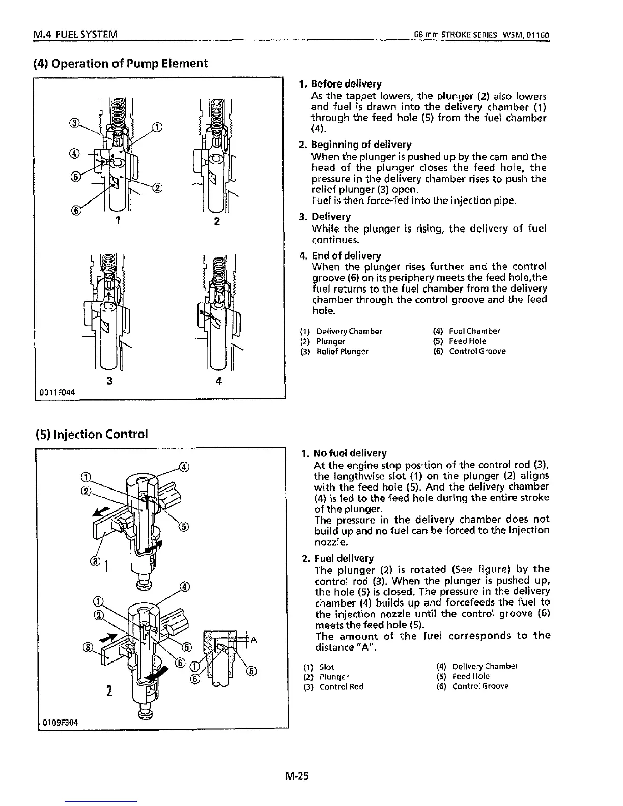
1.
Before delivery
As
the
tappet lowers,
the
plunger
(2)
also
lowers
and fuel
is
drawn into the delivery chamber
(1)
through the feed hole
(5)
from the fuel chamber
(4)
When
the
plunger
is
pushed up by the cam and the
head of the plunger closes the feed hole, the
pressure in the delivery chamber rises to push the
relief plunger
(3)
open.
Fuel
is
then
force-fed into the injection pipe.
While the plunger
is
rising, the delivery of fuel
con
ti
nues.
When the plunger rises further and the control
groove
(6)
on
its
periphery meets the feed hole,the
fuel returns to the fuel chamber from the delivery
chamber through the control groove and the feed
hole.
2.
Beginning of delivery
3.
Delivery
4.
End of delivery
(1)
Delivery Chamber
(4)
Fuel Chamber
(2)
Plunger
(5)
FeedHole
(3)
Relief Plunger
(6)
Control Groove
1.
No
fuel delivery
At the engine stop position
of
the control rod
(3),
the lengthwise slot
(1)
on the plunger
(2)
aligns
with
the feed hole
(5).
And the delivery chamber
(4)
is
led
to
the feed hole
during
the entire stroke
of
the plunger.
The pressure
in
the delivery chamber does not
build
up and no fuel can be forced to
the
injection
nozzle.
The plunger
(2)
is
rotated (See figure) by the
control rod
(3).
When the plunger
is
pushed up,
the hole
(5)
is
closed. The pressure in the delivery
chamber
(4)
builds up and forcefeeds
the
fuel to
the injection nozzle
until
the control groove
(6)
meets
the
feed hole
(5).
The amount of the fuel corresponds to the
distance
"A".
2.
Fuel delivery
(1)
Slot
(2)
Plunger
(3)
Control Rod
(4)
Delivery Chamber
(5)
FeedHole
(6)
Control Groove
M-25