M.4
FUEL
SYSTEM
68
mm
STROKE
SERIES
WSM.01160
[SI
INJECTION
NOZZLE
I
A116F012
[6]
GOVERNOR
I0109F035
(1)
Governor Lever (8) Steel Ball
(2)
Start Spring
(9)
Governor Ball Case
(3) Fork Lever 1 (10) Fuelcamshaft
(4)
Governor Spring (1 1) Idling Ajust
Spring
(5)
Fork Lever
2
(1
2)
Speed Control Lever
(6)
Steel Ball (13) Control Rod
(7)
Governor Sleeve
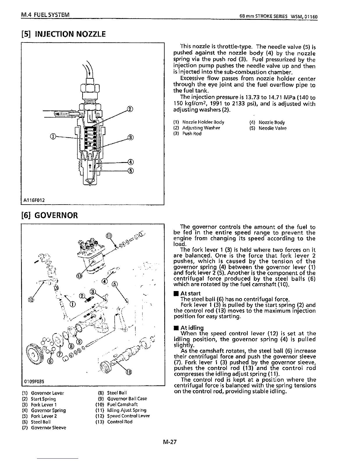
This
nozzle
is
throttle-type. The needle valve
(5)
is
pushed against the nozzle body
(4)
by the nozzle
spring via the push rod
(3).
Fuel pressurized by
the
injection pump pushes the needle valve up and then
is
injected into the sub-combustion chamber.
Excessive flow passes from nozzle holder center
through the eye joint and
the
fuel overflow pipe to
the fuel tank.
The injection pressure
is
13.73
to
14.71
MPa
(140
to
150
kgfkrnz,
1991
to
2133
psi), and
is
adjusted
with
adjusting washers
(2).
(1)
Nozzle Holder Body
(4)
Nozzle Body
(2)
Adjusting
Washer
(5)
Needle Valve
(3)
PushRod
The governor controls the amount of the fuel to
be fed
in
the entire speed range
to
prevent the
engine from changing
its
speed according to the
load.
The fork lever
1
(3)
is
held where two forces on
it
are balanced. One
is
the force
that
fork lever
2
pushes,
which
is
caused by the tension of
the
governor spring
(4)
between the governor lever
(1)
and fork lever
2
(5).
Another
is
the component of
the
centrifugal force produced by the steel balls
(6)
which
are rotated by the fuel camshaft
(10).
At
start
The steel ball
(6)
has no centrifugal force.
Fork
lever
1
(3)
is
pulled by the start spring
(2)
and
the control rod
(13)
moves to the maximum injection
position for easy starting.
At
When
t
e speed control lever
(12)
is
set
at the
idling position, the governor spring
(4)
is
pulled
SI
ightl y.
As the camshaft rotates, the steel ball
(6)
increase
their centrifugal force and push the governor sleeve
(7).
Fork lever
1
(3)
pushed by the overnor sleeve,
pushes the control rod
(13)
and
t
a
e control rod
compresses the idling adjust spring
(1
1).
The control rod
is
kept at a position where
the
centrifugal force
is
balanced
with
the spring tensions
on the control rod, providing stable idling.
M-27