M.4
FUEL
SYSTEM
68
mm
STROKE SERIES
WSM,
01
161
01
09F038
I
0109F039
I
0109F040
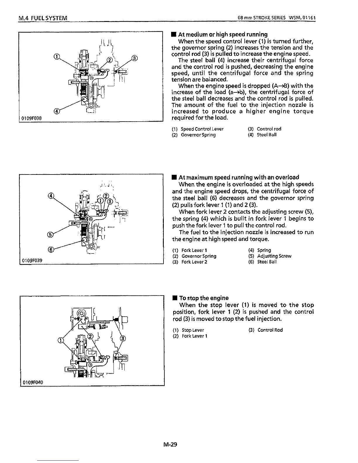
At medium or high speed running
When the speed control lever
(1)
is
turned further,
the governor spring
(2)
increases the tension and the
control rod
(3)
is
pulled to increase the engine speed.
The
steel
ball
(4)
increase their centrifugal force
and the control rod
is
pushed, decreasing
the
engine
speed, until
the
centrifugal force and the spring
tension are balanced.
When the engine speed
is
dropped
(A+B)
with the
increase of
the
load (a+b),
the
centrifugal force of
the
steel
ball decreases and the control rod
is
pulled.
The amount of the fuel
to
the injection nozzle
is
increased to produce a higher engine torque
required for the
load.
(1)
Speed Control
Lever
(3)
Control
rod
(2)
Governor Spring
(4)
Steel Ball
At maximum speed running with
an
overload
When the engine
is
overloaded at
the
high
speeds
and the engine speed drops, the centrifugal force of
the
steel
ball
(6)
decreases and
the
governor spring
(2)
pulls fork lever
1 (1)
and
2
(3).
When fork lever
2
contacts
the
adjusting screw
(S),
the spring
(4)
which
is
built in fork lever
I
begins to
push the fork lever
1
to pull
the
control rod.
The fuel to the injection nozzle
is
increased to run
the engine at high speed and torque.
(1)
Fork Lever
1
(4)
Spring
(2)
Governor Spring
(5)
Adjusting Screw
(3)
Fork Lever
2
(6)
Steel Ball
H
To
stop the engine
When the stop lever
(1)
is
moved to
the
stop
position, fork lever
1
(2)
is
pushed and the control
rod
(3)
is
moved to stop the fuel injection.
(1)
Stop Lever
(3)
Control
Rod
(2)
Fork
Lever
1
M-29