M.5
ELECTRICAL SYSTEM
68 mm STROKE
SERIES
WSM,
01
160
01
09F045
I0109F046
I
01
09F047
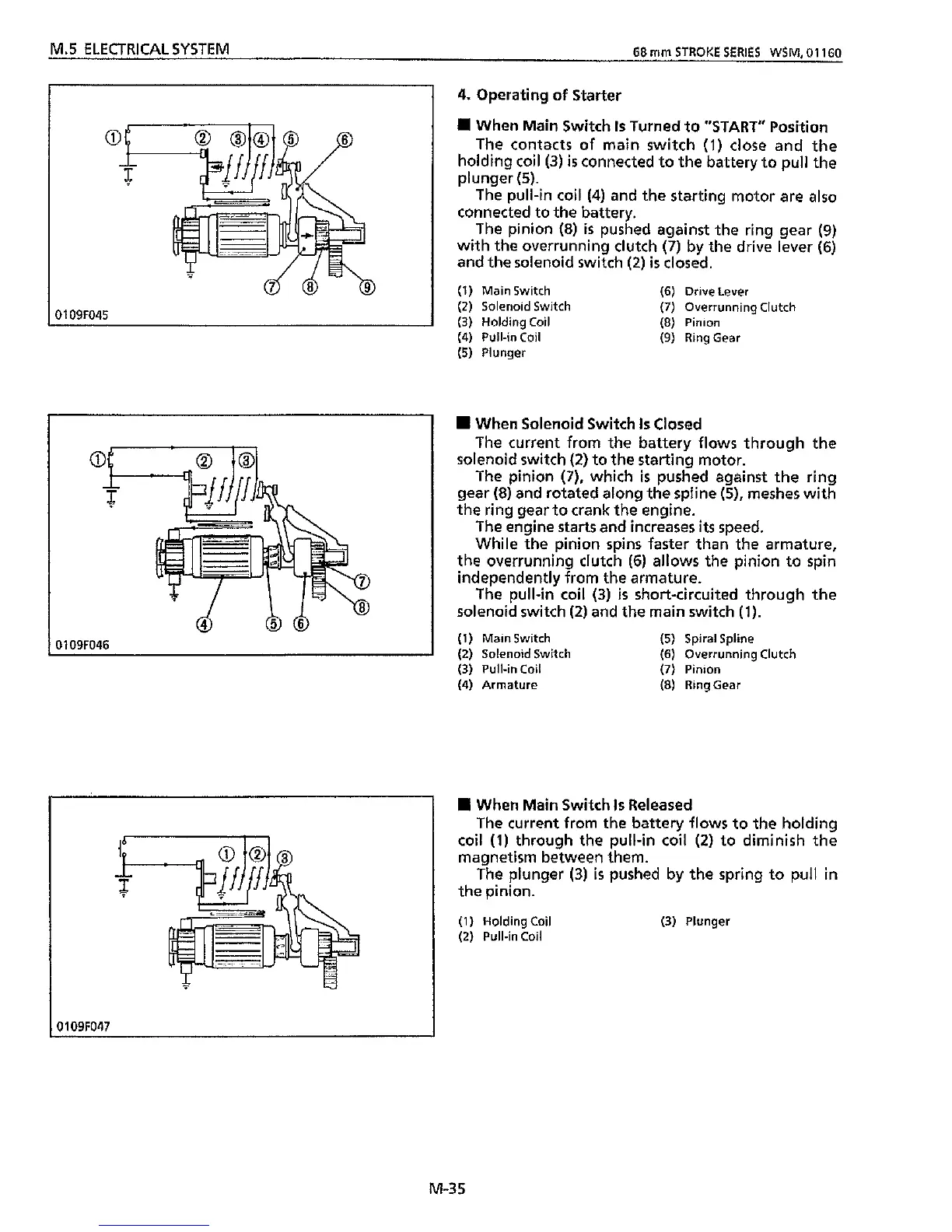
4.
Operating
of
Starter
When Main Switch
Is
Turned to "START" Position
The contacts
of
main switch
(1)
close and the
holding coil
(3)
is
connected to the battery to pull the
plunger
(5).
The pull-in coil
(4)
and the starting motor are
also
connected
to
the battery.
The pinion
(8)
is
pushed against the ring gear
(9)
with the overrunning clutch
(7)
by the drive lever
(6)
and the solenoid switch
(2)
is
closed.
(1)
Main Switch (6) Drive Lever
(2)
Solenoid Switch
(7)
Overrunning Clutch
(3)
Holding Coil
(8)
Pinion
(4) Pull-in Coil (9) RingGear
(5)
Plunger
When Solenoid Switch
Is
Closed
The current from the battery flows through the
solenoid switch
(2)
to the starting motor.
The pinion
(7),
which
is
pushed against the ring
gear
(8)
and rotated along the spline
(5),
meshes with
the ring gear to crank the engine.
The engine
starts
and increases
its
speed.
While the pinion spins faster than the armature,
the overrunning clutch
(6)
allows the pinion to spin
independently from the armature.
The pull-in coil
(3)
is
short-circuited through the
solenoid switch
(2)
and the main switch
(1).
(1)
Main Switch
(5)
Spiral Spline
(2)
Solenoid Switch
(6)
Overrunning Clutch
(3)
Pull-in Coil
(7)
Pinion
(4)
Armature
(8)
RingGear
II
When Main Switch
Is
Released
The current
from
the battery flows to the holding
coil
(1)
through the pull-in coil
(2)
to diminish the
magnetism between them.
The plunger
(3)
is
pushed by the spring to pull in
the pinion.
(1)
Holding
Coil
(3)
Plunger
(2)
Pull-in Coil
M-35