ENGINE
EA330-E4, WSM
1-S32
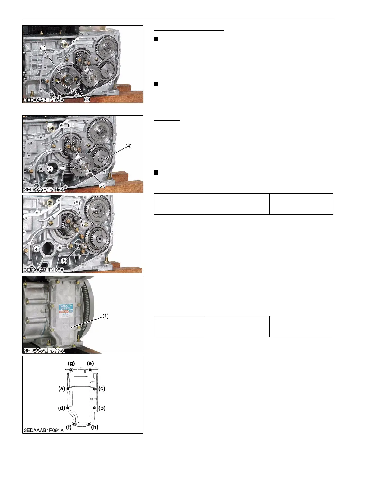
Cam Gear and Camshaft
• Before disassembling, check the backlash of each gears.
Also check them during reassembly.
1. Remove the lock plate mounting screw (2).
2. Remove the cam gear (1) and camshaft together.
(When reassembling)
• Align the alignment marks of each gears.
9Y1211018ENS0043US0
Idle Gear
1. Draw out the external snap ring (3) on the idle gear shaft (6) and
take out the idle gear (2).
2. Alternatively, remove the idle gear shaft screw, and the take out
the idle gear and gear shaft together.
3. Remove the balancer bearing retainer (5).
(When reassembling)
• Align the alignment marks of the idle gear, balancer gear (4)
and crank gear (1).
9Y1211018ENS0044US0
Crankcase Cover
1. Remove the crankcase cover (1).
(When reassembling)
• Tighten the crankcase cover mounting screws gradually in the
order of (a) to (h) as shown in the figure.
9Y1211018ENS0045US0
(1) Cam Gear (2) Lock Plate Mounting Screw
Tightening torque Idle gear shaft screw
9.81 to 11.2 N·m
1.00 to 1.15 kgf·m
7.24 to 8.31 lbf·ft
(1) Crank Gear
(2) Idle Gear
(3) External Snap Ring
(4) Balancer Gear
(5) Balancer Bearing Retainer
(6) Idle Gear Shaft
Tightening torque
Crankcase cover mounting
screw
7.9 to 9.3 N·m
0.80 to 0.95 kgf·m
5.8 to 6.8 lbf·ft
(1) Crankcase Cover
 Loading...