8-M9
M6800 · M6800S · M8200 · M9000, WSM
HYDRAULIC SYSTEM
[2] M8200 · M9000
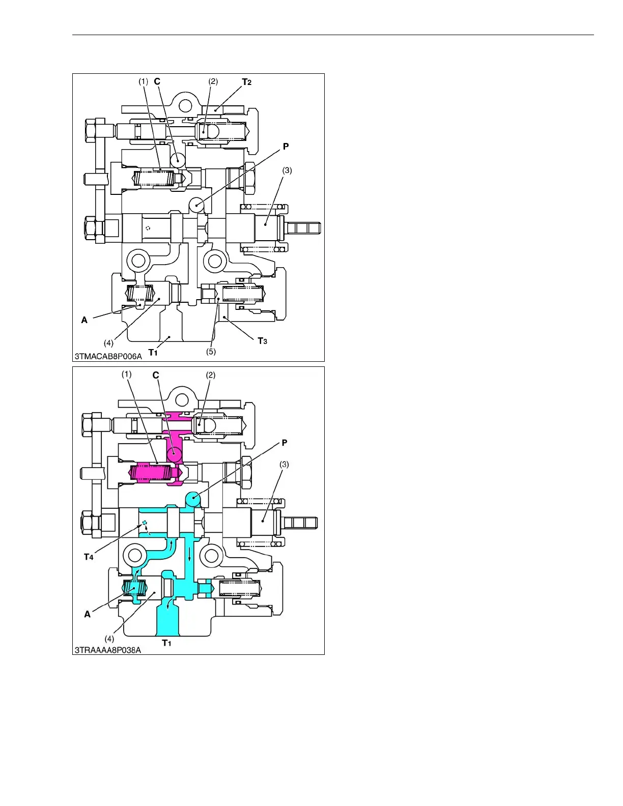
The control valve is composed as shown figure left.
The spool (3) is moved by the operating the position
control lever. The positions of the spool movement
makes four kinds of circuit such as “Neutral”, “Lifting”,
“Lowering” and “Floating”.
Feature of this control valve is smooth operation by
built-in shockless mechanism.
W1014330
Q Neutral
Pressurize oil flows at the P port, pushes open unload
poppet 1 (4) and returns to tank from T
1 port.
The oil in the chamber A behind the unload poppet 1
(4) returns to the tank through the clearance between
spool (3) and T
4 port at the valve body. The oil in the
hydraulic cylinder does not flow out because the circuit is
cut off by the actions of poppet 1 (1), poppet 3 (2).
This allows the implement to be kept at a steady
height.
W1014478
(1) Poppet 1
(2) Poppet 3
(3) Spool
(4) Unload Poppet 1
(5) Unload Poppet 2
P : Pump Port
C : Cylinder Port
T
1 :Tank Port 1
T
2 :Tank Port 2
T
3 :Tank Port 3
A : Chamber A
(1) Poppet 1
(2) Poppet 3
(3) Spool
(4) Unload Poppet 1
P : Pump Port
C : Cylinder Port
T
1 :Tank Port 1
T
4 :Tank Port 4
A : Chamber A



 To Next Page