42 W9232-8135-6
12/2015
Assembly and functions
3. Control lever lock
To enter and leave the operator’s place, the console must be raised by pulling up on the control lever lock.
The engine can only be started if the console is raised. The control levers and the drive levers are only oper-
ational when the console is lowered and the control lever lock is in the "Down" position.
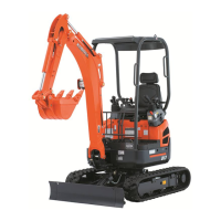
Drive levers and control pedals
Drive levers and control pedals include the following components:
1. Left and right drive levers
2. Boom swing pedal
3. Auxiliary port pedal
Drive levers and control pedals – description
1. Left and right drive levers
With the drive levers the excavator can be driven forwards and backwards and also turned. The left drive lever
c
ontrols the left track and the right drive lever controls the right track.
2. Boom swing pedal
This pedal is used to swing the boom right and left.
3. Auxiliary port pedal
The auxiliary port pedal can be used to operate an attachment.
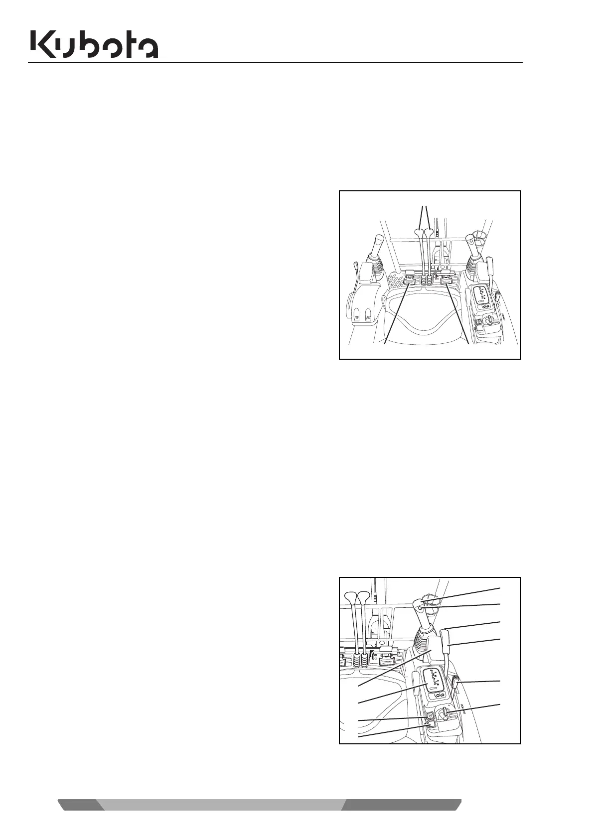
Right control console
The right-hand control console contains the following components:
1. Right control lever
2. Horn switch
3. Travel speed button
4. Dozer control lever
5. Throttle lever
6. Starter switch
7. Rotary beacon button (accessory)
8. Working light button
9. Display and control unit
10. Wrist rest

 Loading...