7
7 http : // www.kvcins.com
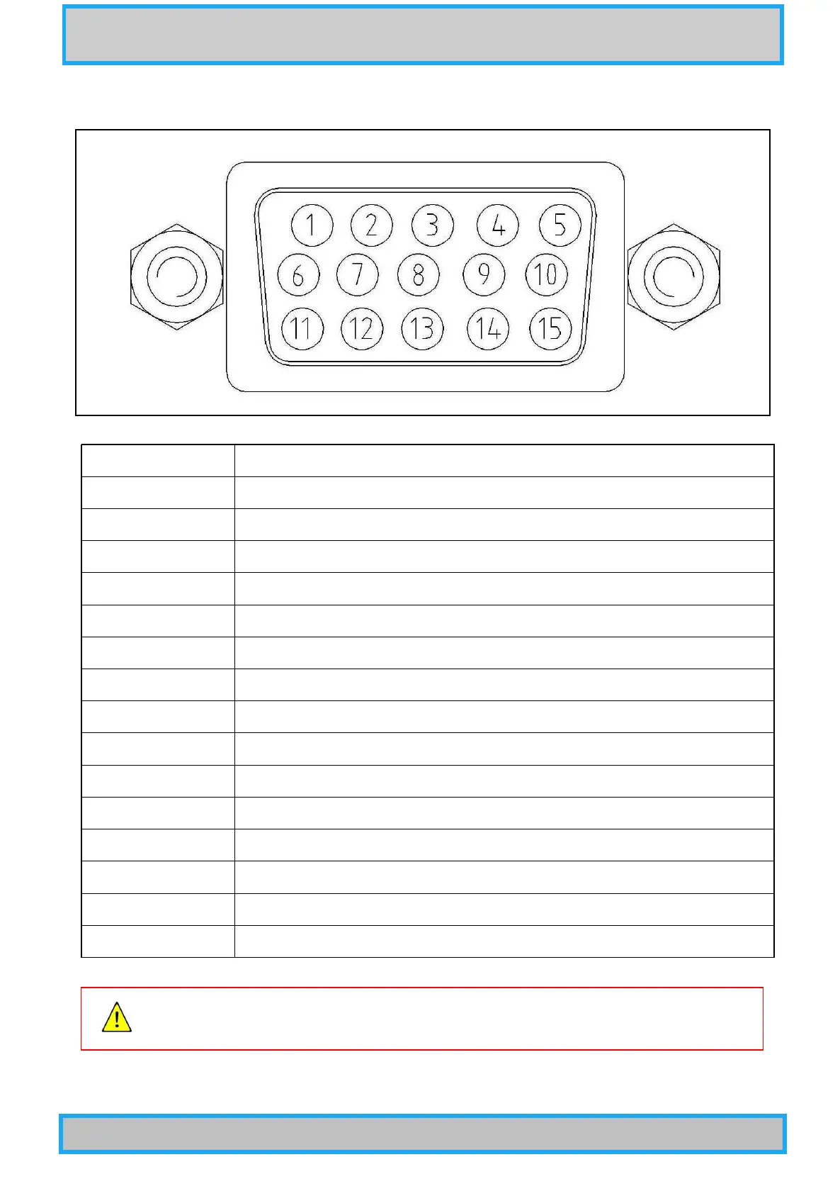
4-2 Connection diagram
PIN NUMBER PIN DESCRIPTION
1 RS485- input
2 RS485+ input
3 Power Input ( 20 ~ 30Vdc )
4 Power Ground
5 Log scale analog output ( 0 ~ 7.18 Vdc for full range )
6 Signal Ground
7 Signal Ground
8 Lin scale analog output ( 0 ~ 10 Vdc between 1.0E-4 ∼ 1 Torr )
9 No connection
10 Relay1 Normally Open
11 Relay2 Normally Open
12 Relay2 common
13 Communication ground
14 Case pannel ground ( FG )
15 Relay1 common
For safety and stable operation of the instrument, make sure to ground PIN 14.