EasyManuals Logo

KVH Industries TracVision 4 Installation & Maintenance Manual

KVH Industries TracVision 4
95 pages
To Next Page IconTo Next Page
To Previous Page IconTo Previous Page
Page #34 background imageLoading...
Page #34 background image
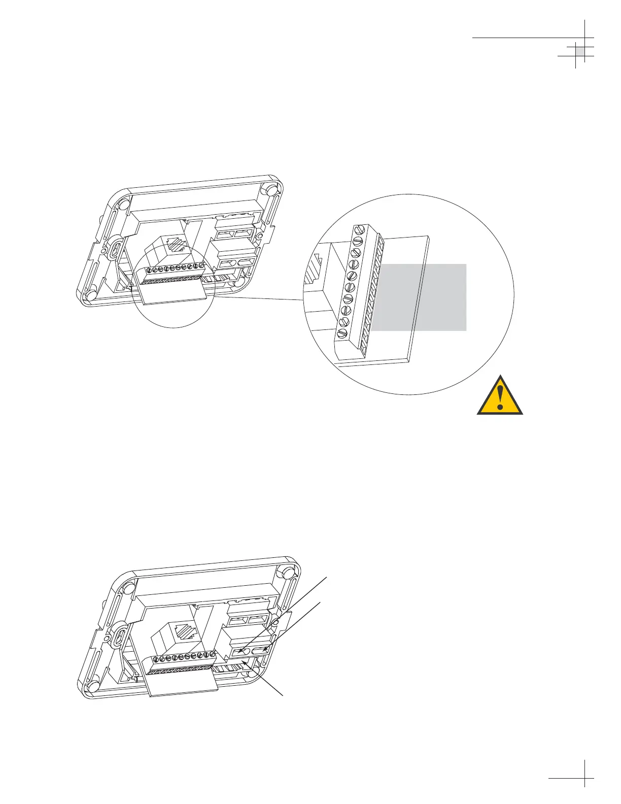
Connecting the Antenna Data Cable
Find the TracVision 4 data cable where it comes through the
panel cutout made earlier. Wire the data cable to the switchplate
as shown in Figure 2-13. The connector board is etched with the
same wire color identification to make the wiring process easier.
Connecting the Antenna Power Cable
Find the TracVision 4 power cable where it comes through the
panel cutout made earlier. Wire the antenna unit power cable to
the switchplate connectors as shown in Figure 2-14. After wiring
the power cable, connect the power indicator lamp, also as noted
in Figure 2-14. After both the power cable and lamp are properly
wired, carefully insert the lamp into its socket immediately below
the switchplate connectors.
Installation
54-0150
23
BLU/WHT Not Used
WHT/BLU Not Used
BRN/WHT PC GND
WHT/BRN PC TXD
ORG/WHT PC RXD
WHT/ORG RF GND
GRY/WHT RF RXD
WHT/GRY RF TXD
GRN/WHT Not Used
WHT/GRN Not Used
Data Cable
to Antenna
Figure 2-13
Data Cable Wiring Arrangement
+12 VDC (Red)
+12 VDC – Lamp
Ground (Black)
Ground – Lamp
Lamp Socket
Figure 2-14
Wiring the Antenna Unit Power
Cable and Indicator Lamp
Cut back and insulate any unused
wires from the Data Cable.

Table of Contents

Other manuals for KVH Industries TracVision 4

Questions and Answers:

Question and Answer IconNeed help?

Do you have a question about the KVH Industries TracVision 4 and is the answer not in the manual?

KVH Industries TracVision 4 Specifications

General IconGeneral
BrandKVH Industries
ModelTracVision 4
CategorySatellite TV System
LanguageEnglish

Related product manuals