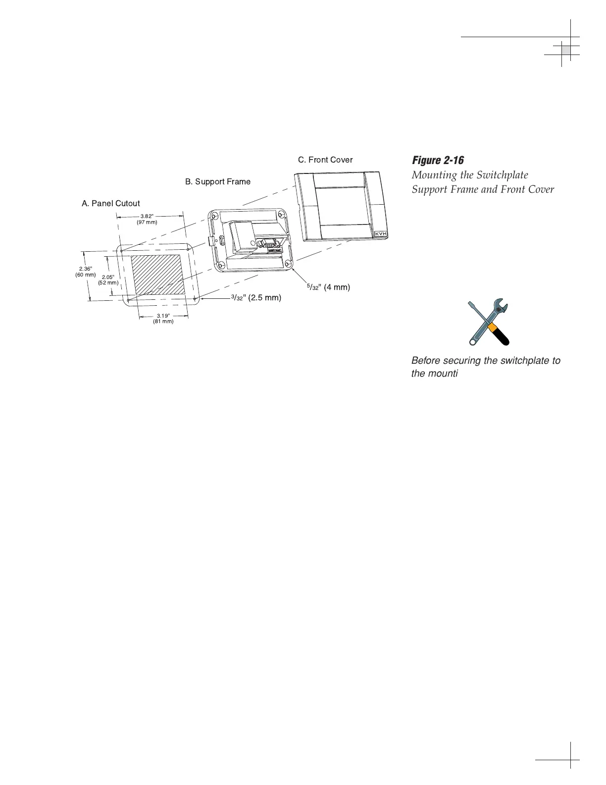
2.5 Mounting the Switchplate
After completing the switchplate wiring process, you must install
the switchplate itself. This process, detailed in the following
steps, is illustrated in Figure 2-16.
1. Fit the switchplate assembly and support frame
into the panel cutout made earlier and flush to the
mounting surface.
2. Drill out four
5
⁄32" (4 mm) holes in the countersunk
settings in the switchplate support frame.
3. Drill four
3
⁄32" (2.5 mm) holes in the mounting
surface using the countersunk holes in the support
frame as the template. Secure the support frame
and switchplate assembly to the mounting surface
using the four #6 self-cutting screws.
4. Snap the front cover into place to cover the screws
and support frame.
5. Reconnect vessel power.
Installation
54-0150
25
Figure 2-16
Mounting the Switchplate
Support Frame and Front Cover
Before securing the switchplate to
the mounting surface, be sure to
strain relieve the wires connecting
to the switchplate connectors.
Several tie-wraps have been
provided to aid in strain relieving
the wires.

 Loading...


