EasyManuals Logo

KVH Industries TracVision 4 Installation & Maintenance Manual

KVH Industries TracVision 4
95 pages
To Next Page IconTo Next Page
To Previous Page IconTo Previous Page
Page #64 background imageLoading...
Page #64 background image
Maintenance
54-0150
57
Replacing a Fuse
Two 5x20 mm, 3.15-amp, 250-volt fast-blow fuses are mounted to
the main PCB (see Figure 4-3 on page 55). If one of these fuses
has blown or been broken, simply remove the bad fuse and
replace with a good fuse of the same rating.
4.5 Replacing the RF PCB
1. The RF PCB receives operating voltages from both
the main PCB and the IRD (via the RF cable).
Ensure that all power (including the IRD) is
turned off before proceeding.
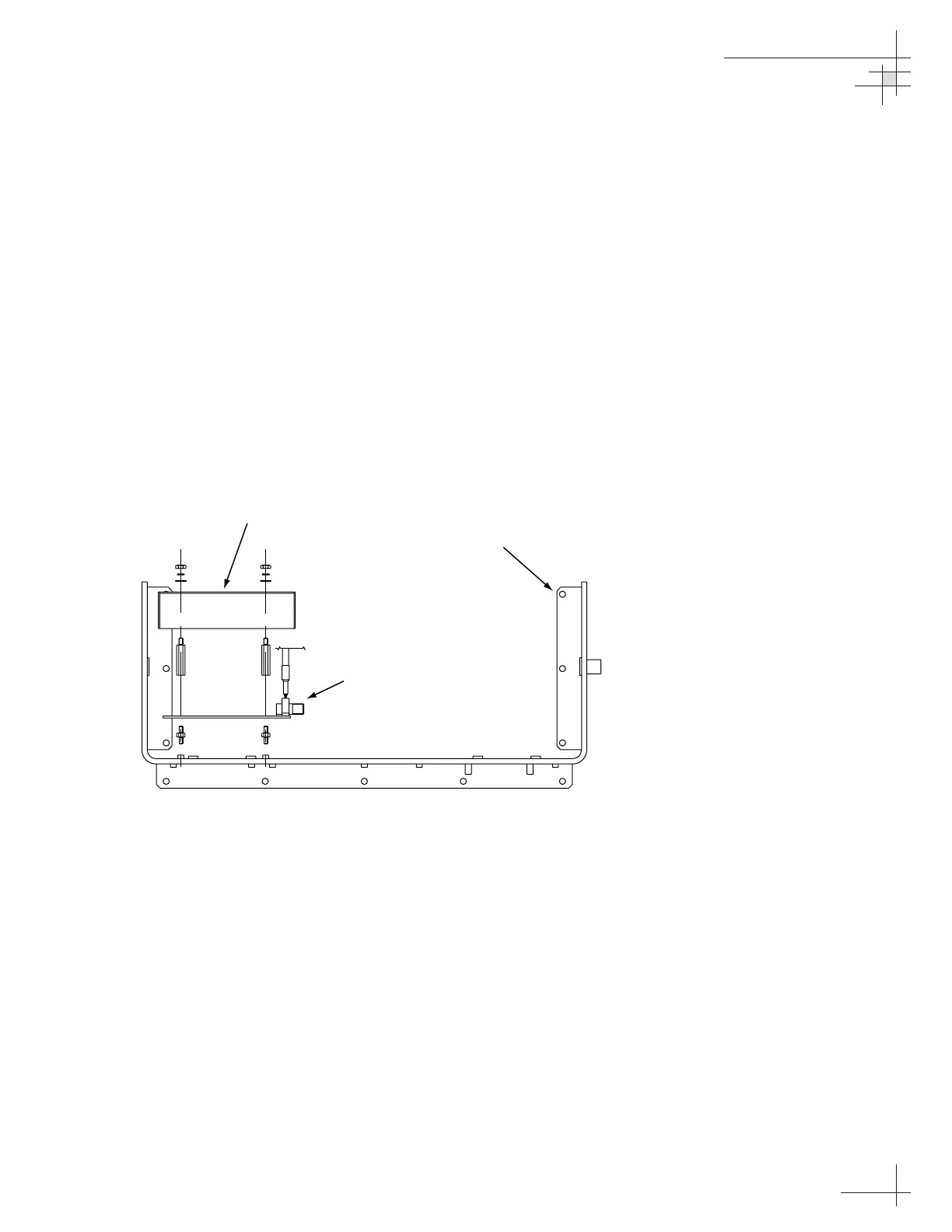
2. Using a
5
16" socket wrench, remove the four nuts
and washers securing the RF PCB cover (see
Figure 4-5). Set the hardware and cover aside.
RF PCB Cover
Support Frame
RF PCB
Figure 4-5
RF PCB Mounting (Top View)

Table of Contents

Other manuals for KVH Industries TracVision 4

Questions and Answers:

Question and Answer IconNeed help?

Do you have a question about the KVH Industries TracVision 4 and is the answer not in the manual?

KVH Industries TracVision 4 Specifications

General IconGeneral
BrandKVH Industries
ModelTracVision 4
CategorySatellite TV System
LanguageEnglish

Related product manuals