EasyManuals Logo

KVH Industries TracVision 4 Installation & Maintenance Manual

KVH Industries TracVision 4
95 pages
To Next Page IconTo Next Page
To Previous Page IconTo Previous Page
Page #60 background imageLoading...
Page #60 background image
The antenna unit’s printed circuit boards (PCBs), gyro, LNB,
elevation motor, and elevation drive belt may be removed and
replaced on site using common hand tools. Other TracVision 4
service must be done by your authorized dealer/installer,
distributor or by KVH. Evidence of tampering or unauthorized
repairs will void the warranty. The following sections provide
step-by-step procedures for removing and replacing field
replaceable units.
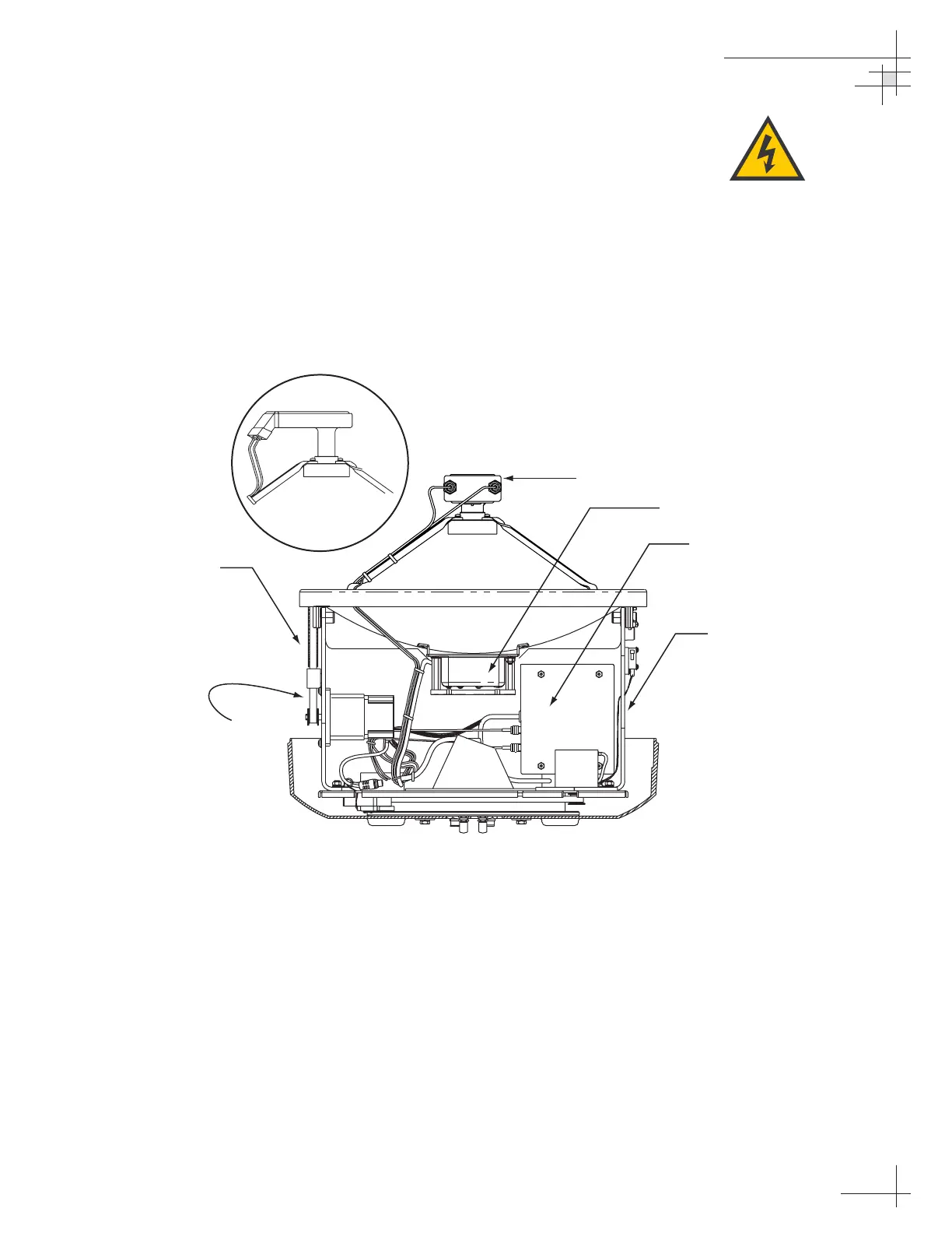
Figure 4-1 depicts the location of a number of components within
the TracVision 4 antenna unit.
Maintenance
54-0150
53
TracVision 4 components receive
power from multiple sources. Do
not open any electrical
assemblies or attempt servicing
until IRD power and vessel input
power are disconnected.
Antenna Gyro
RF Board and Cover
Antenna Support Frame
Elevation Drive
Motor Assembly
European LNB
PCB Cover
and CPU
U.S.-style
LNB
Figure 4-1
TracVision 4 Antenna Unit
(Baseplate Cut Away)

Table of Contents

Other manuals for KVH Industries TracVision 4

Questions and Answers:

Question and Answer IconNeed help?

Do you have a question about the KVH Industries TracVision 4 and is the answer not in the manual?

KVH Industries TracVision 4 Specifications

General IconGeneral
BrandKVH Industries
ModelTracVision 4
CategorySatellite TV System
LanguageEnglish

Related product manuals