5-10
NOTE: Make sure that the ignition switch is in the
ON position, transmission in neutral, brake lock
released, and the emergency stop switch in the
RUN position.
3. Depress the starter button while observing the
multimeter. The multimeter should drop to 0 volts,
a “click” should be heard from the relay, and the
starter motor should run.
NOTE: If a “click” is heard and any voltage is indi-
cated by the multimeter, replace the starter relay. If
no “click” is heard and the multimeter continues to
indicate battery voltage, test the neutral start relay.
Starter Motor
NOTE: The starter is a non-serviceable compo-
nent. If the following test does not result as speci-
fied, the starter must be replaced.
TESTING VOLTAGE
Perform this test on the starter motor positive terminal.
To access the terminal, slide the boot away.
NOTE: The ignition switch must be in the ON
position, the emergency stop switch in the RUN
position, and the shift lever in the NEUTRAL posi-
tion.
1. Set the meter selector to the DC Voltage position.
2. Connect the red tester lead to the starter terminal;
then connect the black tester lead to ground.
3. With the starter button depressed, the meter must
show approximately 10.0 DC volts and the starter
motor should operate.
AR607D
NOTE: If the meter showed correct voltage but
the starter did not operate or operated slowly, the
starter motor is defective.
NOTE: If the meter showed no voltage, inspect
ground connections, starter motor lead, battery
voltage (at the battery), starter relay, or the neutral
start relay.
REMOVING
1. Disconnect the battery.
2. Remove the nut securing the positive cable to the
starter; then remove the cable from the starter.
3. Remove the two cap screws securing the starter to
the crankcase; then remove the starter. Account for
an O-ring.
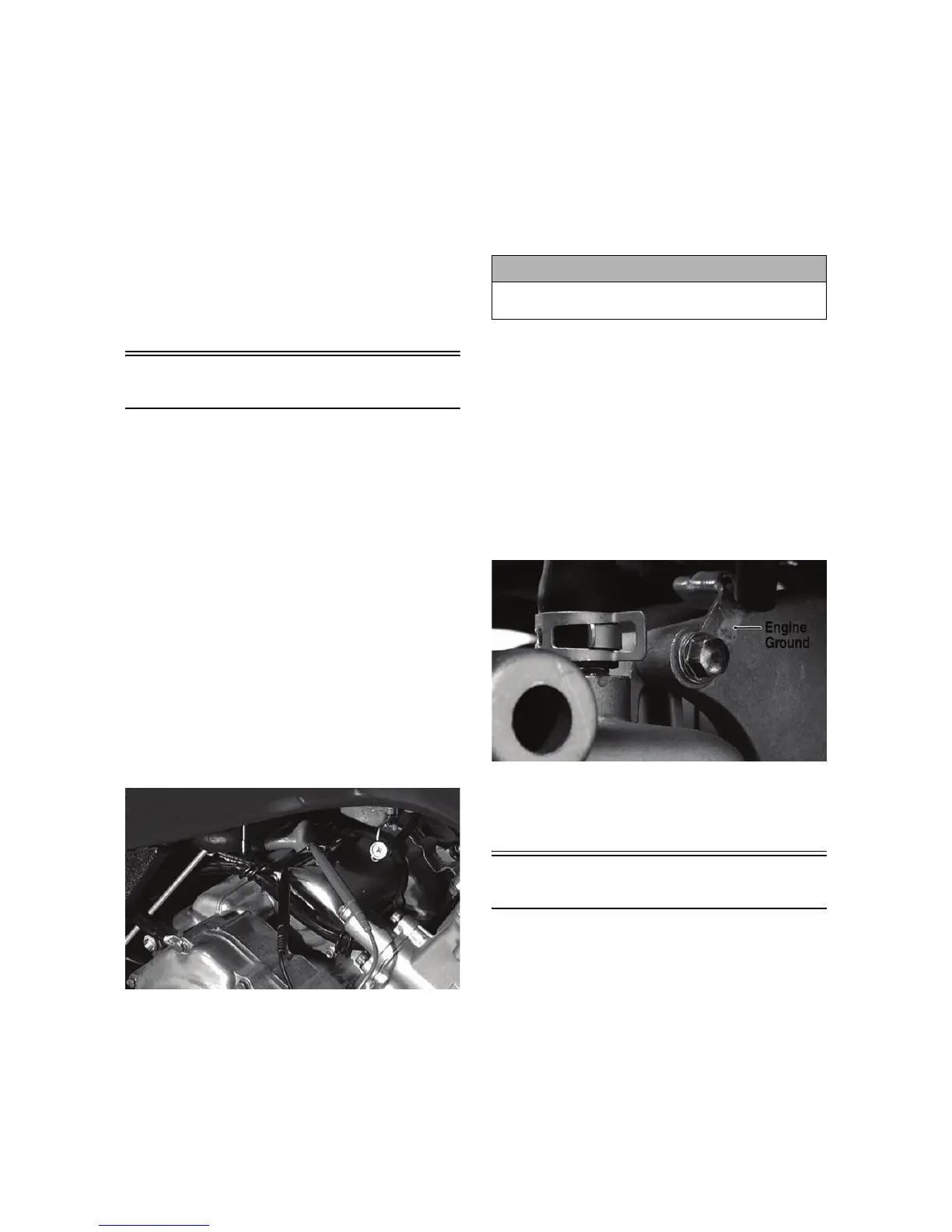
INSTALLING
1. Apply a small amount of grease to the O-ring seal
on the starter; then install the starter into the crank-
case. Secure with two cap screws making sure the
engine ground is secured by the rear cap screws.
Tighten to 8 ft-lb.
KC201A
2. Secure the positive cable to the starter with the
nut. Tighten to 8 ft-lb.
3. Connect the battery.
CDI Unit
The CDI is located on the electrical tray in front of the
steering post.
NOTE: The CDI unit is not a serviceable compo-
nent. If the unit is defective, it must be replaced.
The CDI is rarely the cause for electrical problems;
however, if the CDI is suspected, substitute another
CDI unit to verify the suspected one is defective.
! CAUTION
Always disconnect the negative battery cable from
the battery first; then disconnect the positive cable.