5-12
1. Set the meter selector to the DC Voltage position.
2. Connect the black tester lead to the black wire;
then connect the red tester lead to the brown/blue
wire.
3. The meter must show battery voltage.
NOTE: If the meter does not show voltage,
inspect fuses, wiring harness, connectors, and
switches.
VOLTAGE (Brakelights)
NOTE: Perform this test on the main harness side
of the connector. Also, the ignition switch should
be in the ON position and the brake (either foot
pedal or hand lever) must be applied.
1. Set the meter selector to the DC Voltage position.
2. Connect the black tester lead to the black wire;
then connect the red tester lead to the green/yellow
wire.
3. The meter must show battery voltage.
NOTE: If the meter does not show voltage,
inspect bulb, fuses, wiring harness, connectors,
and switches.
Running Lights
The two running lights use the same connectors as the
headlights (see Headlights in this section).
VOLTAGE
1. Release the wire connector from the frame; then
release and separate the connectors.
NOTE: Perform this test on the wiring harness
side of the connectors.
2. Connect the black tester lead of the meter to the
black wire; then with the tester in the DC Volts
position, connect the red tester lead to the
brown/black wire.
3. Turn the ignition switch to the LIGHTS position.
The meter must show battery voltage.
NOTE: If the meter does not show voltage,
inspect the LIGHTS fuse, battery connections, or
troubleshoot the main wiring harness.
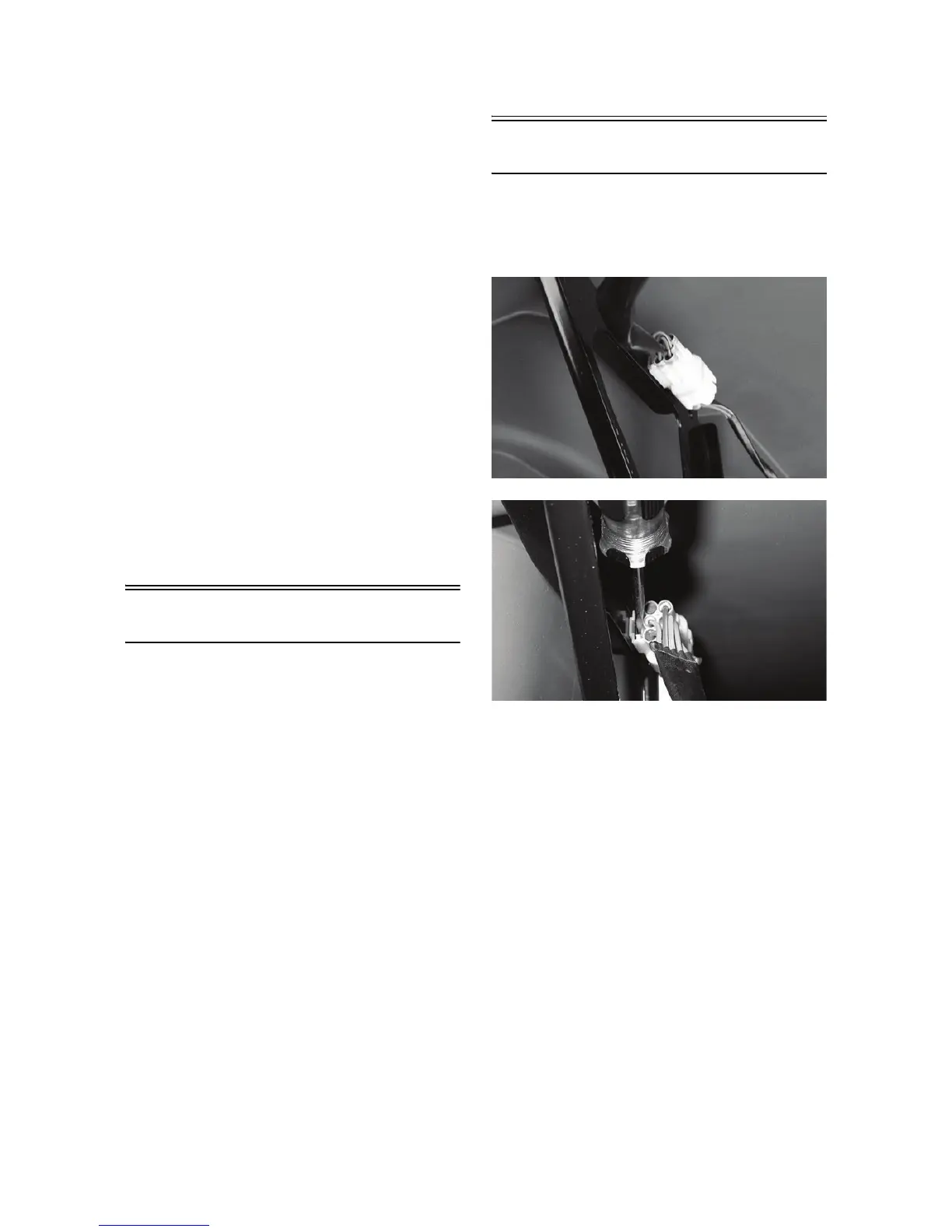
Back-Up Lights
The back-up lights connectors are located on the rear
frame supports attached by a metal tab. They may be
released from the frame by depressing the release with
a small screwdriver.
KC279
KC280
VOLTAGE
1. Release the wire connectors from the frame; then
disconnect the connectors.
NOTE: Perform this test on the main harness side
of the connectors.
2. Connect the black tester lead to the brown/laven-
der wire; then connect the red tester lead to the
lavender/red wire.
3. Set the tester to DC VOLTS; then turn the ignition
switch to the ON position and move the shift lever
to the R (reverse) position. The meter must show
battery voltage.
NOTE: If the meter does not show battery volt-
age, use the following procedure to troubleshoot.
4. Remove the black tester lead from the brown/lav-
ender wire and connect to a suitable ground.