Do you have a question about the Kyocera DF-770 and is the answer not in the manual?
Warns about risks of incorrect battery replacement and proper disposal of used batteries.
Explains the booklet's purpose for service personnel safety during maintenance.
Defines DANGER, WARNING, CAUTION symbols and their meanings.
Details safe power supply usage, grounding, and extension cable guidelines.
Specifies suitable installation locations and machine handling procedures.
Outlines steps before starting maintenance, like unplugging power and disabling safety features.
Provides guidance on handling parts, specifications, and sensitive components.
Advises on safe clothing, working with powered machines, and handling hot parts.
Warns against heating the drum or using improper solvents, and details solvent handling.
Details machine type, trays, paper weight, dimensions, and overall weight.
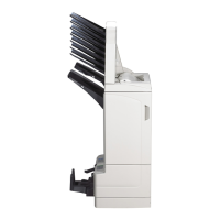
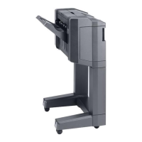
Illustrates and labels the main parts of the document finisher.
Illustrates and labels the main parts of the bridge unit.
Shows a cross-section illustrating the paper path and major components.
Specifies conditions for machine placement, temperature, humidity, and air quality.
Step-by-step guide for unpacking the document finisher unit.
Step-by-step guide for unpacking the bridge unit.
Instructions for removing packing tapes and protective pads from the units.
Describes the procedure for entering and running specific maintenance tasks via the control panel.
Lists available maintenance modes, item numbers, and their initial settings.
Details how to display ROM versions of various machine components.
Explains how to check operational counts for optional devices like finishers.
Explains how paper misfeeds are displayed and indicates potential jam locations.
Describes the machine's self-diagnostic capabilities and error message reporting.
Lists specific error codes and conditions related to paper misfeeds in the bridge unit.
Details troubleshooting for punch motor errors (Codes 8010, 8020).
Details troubleshooting for paddle and tray motor errors (Codes 8030, 8090).
Details troubleshooting for shift and eject motor errors (Codes 8100-8120).
Details troubleshooting for shift release and tray motor errors (Codes 8130, 8140).
Details troubleshooting for tray motor errors 2 and 3 (Codes 8150, 8160).
Details troubleshooting for DF side registration motor errors (Codes 8170, 8180).
Details troubleshooting for DF side registration motor errors (Codes 8190, 8200).
Details troubleshooting for slide and staple motor errors (Codes 8210, 8230).
Details troubleshooting for finisher communication and backup errors (Codes 8800, 8900).
Troubleshooting for DF middle, eject, paddle, and eject release motors not operating.
Troubleshooting for DF eject, adjustment, slide, and tray motors not operating.
Troubleshooting for bridge unit motors, solenoid, and staple unit sensor issues.
Identifies causes of paper jams and methods for correction, including roller cleaning.
Addresses troubleshooting steps for abnormal noises from rollers, pulleys, and gears.
Covers safety measures before disassembly, static charge, PWB handling, and screw usage.
Steps to remove the front and lid rear covers of the document finisher.
Steps to remove the DF rear cover.
Procedure for detaching, refitting, and handling the EEPROM on the PF main PWB.
Steps for removing and refitting the staple unit, including connector handling.
Detailed steps for lifting and pulling the staple unit for removal.
Specific instruction to transfer the EEPROM when replacing the finisher PWB.
Describes the parts and function of the bridge unit section.
Illustrates the electrical connections and signal flow within the bridge unit.
Describes the parts and function of the processing section for bundle discharge and staple modes.
Illustrates the electrical connections and signal flow within the processing section.
Explains the paper feeding, guide adjustment, and bundle discharge process.
Describes the parts and function of the eject tray section for stocking paper.
Illustrates the electrical connections and signal flow within the eject tray section.
Identifies the main parts of the optional punch unit.
Illustrates the electrical connections and signal flow within the punch unit.
Identifies the location and function of the DF main PWB.
Lists and describes the function of various switches and sensors in the finisher.
Lists and describes the function of all motors within the finisher unit.
Identifies the components within the bridge section, including sensors and motors.
Identifies the components within the punch unit, including sensors, motors, and solenoid.
Details pin assignments, signals, and voltage for the DF Main PWB.
Details pin assignments, signals, and voltage for the Bridge PWB.
Details pin assignments, signals, and voltage for the Punch Unit PWB.
Presents the comprehensive wiring diagram for the entire system, showing interconnections.