Do you have a question about the Kyongbo Electronics GDR-D01 and is the answer not in the manual?
Indicates potential for death or serious injury.
Indicates potential for injury or property damage.
Symbol for prohibited actions.
Symbol for required actions.
Rated voltage and overload endurance of the input.
Specifications for control source voltage, overload, and burden.
Operational frequency range for the relay.
Details on case structure, color, and material.
UnderVoltage protection operation value, time, and mode settings.
Capacity and material details for trip and signal output contacts.
Insulation resistance and withstand voltage test specifications.
Test parameters for vibration, shock, and earthquake resistance.
Noise endurance test specifications (EFT, Surge, RF).
Operation and recovery conditions for temperature and humidity.
Environmental conditions for relay operation, including altitude and dust.
UnderVoltage protection with inverse and definite time characteristics.
Voltage metering capabilities, including range and display.
Overview of RS-232C and RS-485C communication methods.
RS-232C circuit, connection, and cable requirements.
RS-485C communication, multi-drop, and termination resistor details.
Relay operation monitoring and main diagnosis categories.
Function for displaying accumulated operation and fault data.
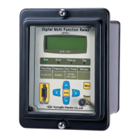
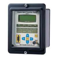
Front panel components: LCD, LEDs, keypad, and connector.
Keypad functions and RS-232C connector details.
Explanation of Run, Error, Pick-up, and Trip LED indicators.
Key operations, LCD structure, initial display, and menu tree navigation.
Overview of the 7 main categories for relay settings.
Displaying measured voltage on the measurement screen.
Accessing and setting UnderVoltage protection functions.
Detailed settings for the UnderVoltage element.
Displaying self-diagnosis results for various categories.
Configuring RS-485 communication settings.
Setting details for Power system, T/S Output, and Password.
Setting system frequency and phase/PT ratio.
Configuring connection types and recovery delay for output connections.
Changing the system configuration password.
Displaying and managing recorded fault data.
Viewing the details of the most recent fault record.
Deleting stored fault content.
Performing tests on display and connection outputs.
Checking the condition of LCD and LEDs on the front panel.
Checking connection outputs by changing their states.
Overview of SetGDRSeries program menus for communication and settings.
Selecting the GDR Series relay for software communication.
Configuring communication ports and slave addresses.
Screen for selecting Setting, Status, and Report functions.
Setting relay elements and system configuration.
Viewing relay status: voltage, fault record, and operational states.
Storing and reading relay data as text files.
| Brand | Kyongbo Electronics |
|---|---|
| Model | GDR-D01 |
| Category | Relays |
| Language | English |