COMPONENT MAINTENANCE MANUAL
AVIATION RECORDERS
Model FA5000
Initial Issue Page 313
Sep. 30/11
Disassembly
23–70–40
Use or disclosure of information on this sheet is subject to
the restrictions on the cover page of this document.
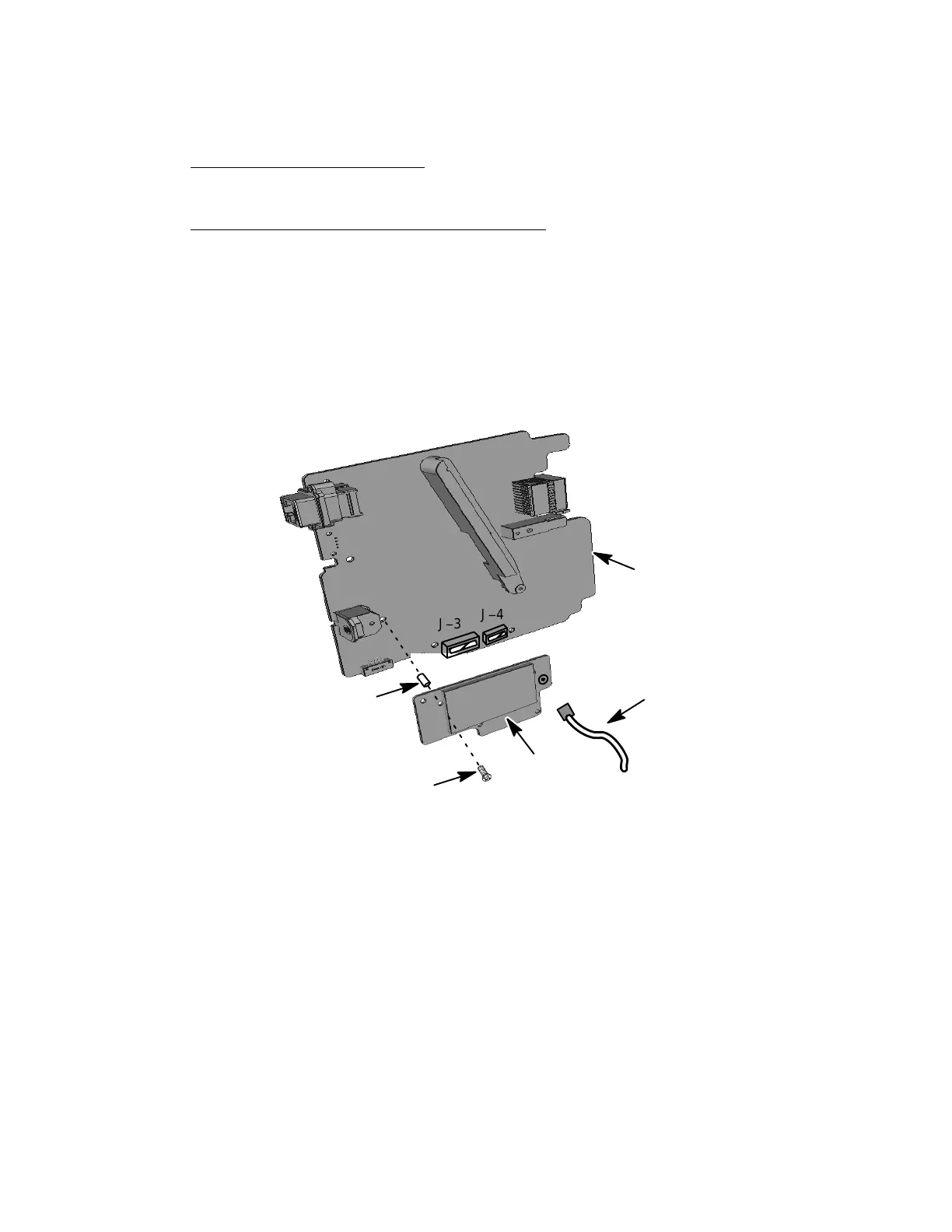
F. Video Card PWA Removal (for P/N: 5001−6133−11 only)
(See 306 or IPL Figure 1, Item 175)
VIDEO CARD PWA REMOVAL PROCEDURE
(1) Remove the MP PWA (1−50) as described in Paragraph E, Main Processor
PWA Removal.
(2) Remove the eight screws (1−180) and three stand−off (1−185) used to secure
the Video Card PWA (1-175) to the MP PWA (1−50).
(3) Remove the Video Card PWA (1-175) from the J−3 and J−4 connectors on the
MP PWA (1−50). Remove the video cable (1−190) from the Video Card PWA.
(1−185)
(1−180)
Some parts are removed
for clarity purposes
NOTE:
(QTY 3)
(QTY 8)
J−3
J−4
(1−175)
(1−50)
(1−190)
Figure 307.
Main Processor (MP) PWA Removal Diagram
The document reference is online, please check the correspondence between the online documentation and the printed version.