COMPONENT MAINTENANCE MANUAL
AVIATION RECORDERS
Model FA5000
Initial Issue Page 712
Sep. 30/11
Assembly
23–70–40
Use or disclosure of information on this sheet is subject to
the restrictions on the cover page of this document.
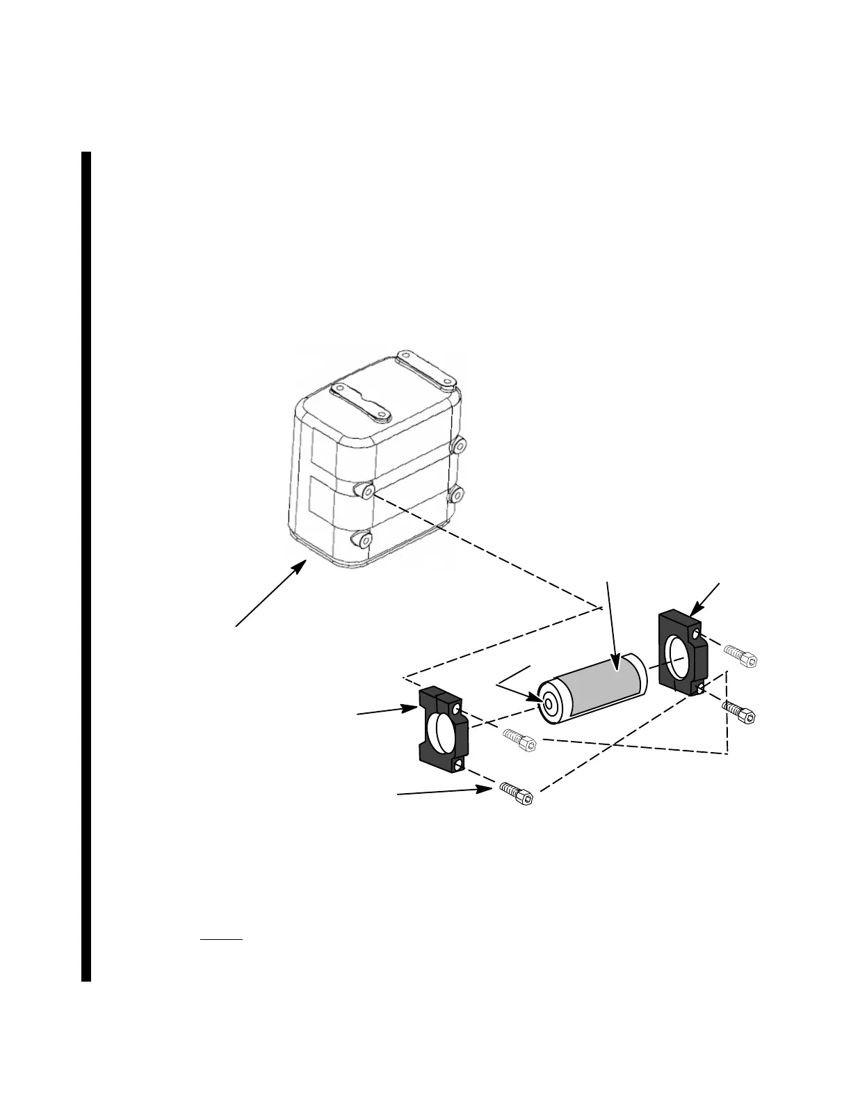
(2) Apply Loctite, Table 701 Item1, to four 1/4–20, 1” hex-cap screws (1-150).
(3) Attach the Beacon (1-155) and Beacon Mount Brackets (1-145) with the four
hex-cap screws (150). Torque mounting bolts (1-150) in a cross−pattern as
shown in Figure 706 to 75 in/lbs.
(4) Perform the ULB operation test using P/N: 17TES0015, as described in Section
100 of this CMM.
Left Beacon
Mount Bracket
(1-145)
Right Beacon
Mount Bracket
(1-145)
Underwater
Locator Beacon
(1-155A/B)
1/4” Hex Screw
(1-150)
Crash Survivable
Memory Unit
(CSMU)
(1-120)
Water Switch
#1
#4
#2
#3
Cross-Pattern
Torquing Sequence
(75 in./lbs.)
Figure 706.
Underwater Locator Beacon Assembly
NOTE: For complete testing of the ULB and battery replacement
procedures, refer to the 90-Day Underwater Locator Beacon
CMM, L-3 PN: 165-E5542-00.
Rev. 06 Page 712
Mar. 16/16
The document reference is online, please check the correspondence between the online documentation and the printed version.