COMPONENT MAINTENANCE MANUAL
AVIATION RECORDERS
Model FA5000
Initial Issue Page 708
Sep. 30/11
Assembly
23–70–40
Use or disclosure of information on this sheet is subject to
the restrictions on the cover page of this document.
(1−20)
(1−25)
(Qty. 2)
(Qty. 4)
(1−10)
(1−30)
Some parts are removed
for clarity purposes
NOTE:
Connector
(1−50)
(1−5)
(REF,)
(1−20)
(1−15)
(Qty. 2)
(1−190)
VIDEO
ONLY
Connector
Guide Pin
Torque
(9−10in/lbs)
Torque
(9−10in/lbs
Torque
(9−10in/lbs)
(Qty. 4)
(1−100)
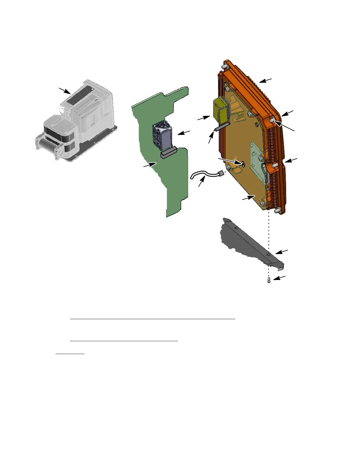
Figure 704.
Rear Cover Installation Diagram
F. Crash Survivable Memory Unit (CSMU) Installation
(See Figure 705 or IPL Figure 1, Item 120)
CSMU INSTALLATION PROCEDURE
CAUTION: The following procedures must be adhered to so that no damage to the
CSMU memory cable or CSMU occurs. Support the CSMU when in-
stalling the six screws (1−125). Do not let the CSMU drop.
(1) Place the Recorder in up−side down position.
(2) Carefully guide the CSMU (1−120) cable thru the slot in the Mounting Chassis
(1−100).
The document reference is online, please check the correspondence between the online documentation and the printed version.