COMPONENT MAINTENANCE MANUAL
AVIATION RECORDERS
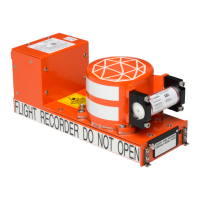
Model FA5000
Initial Issue Page 704
Sep. 30/11
Assembly
23–70–40
Use or disclosure of information on this sheet is subject to
the restrictions on the cover page of this document.
(4) Install the one cover (1−60), screw (1−65), spacer (1−70) and two springs
(1−75) used to secure the top half Ethernet connector J−2 to the front part of
the Shielded Housing (1−5). Tighten screw to a torque value of 2−3 in./lbs.
(5) Install the two screws (1−135) used to secure the Seal Pad (1−140) and the
CSMU cable (1−120) connector to the MP PWA (1−50). Tighten screws to a
torque value of 5-6 in./lbs.
(6) Install CSMU cable cover plate (1-110) and secure using the two screws
(1−115). Tighten screws to a torque value of 5-6 in./lbs.
(7) Connect the RIPS cable (1−85) at P−5 on the MP PWA (1−50).
(8) Connect the Hold−up Capacitor cables at J−6 (RED) and J−7 (BLACK) on the
MP PWA (1−50).
(9) Install the rear cover (1−10) as described in Paragraph E, Rear Cover Installa-
tion.
The document reference is online, please check the correspondence between the online documentation and the printed version.