COMPONENT MAINTENANCE MANUAL
AVIATION RECORDERS
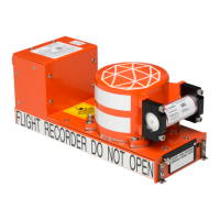
Model FA5000
Initital Issue Page 22
Sep. 30/11
Description and Operation
23–70−40
Use or disclosure of information on this sheet is subject to
the restrictions on the cover page of this document.
44 +28VDC INPUT
SECONDARY
IN +28VDC power supply secondary input per
TNX131AF329E10, Section 3.4.2.5
(FAR 29.1459 (a) (6))
45 AREA MICROPHONE
POWER RETURN
IN Connected to Pin 38,
AREA_MICROPHONE_SIGNAL LOW, through a
0 Ohm resistor.
46 AREA MICROPHONE
SIGNAL SHIELD GROUND
RETURN
IN Connected to Pin 38, AREA MICROPHONE
SIGNAL LOW, through a 0 Ohm resistor.
47 PUSH TO TEST IN Grounding initiates self test. Signal is a shunt dis
crete input. ARINC 7574, Attachment 5. Internally
pulled up to 19VDC and diode isolated; threshold
greater than 100K Ohms to standard ground when
asserted. Source current is 0.2mA.
GND = SELF TEST
OPEN = NO SELF TEST
48 6dB CAM INPUT
ATTENUATION
IN For internal microphone preamplifier gain selec
tion. Jumper Common Pin 54 to pins 48, 49, 50
individually or combined to hardware decode one
of eight possible attenuations. See Table A2 be
low.
49 12dB CAM INPUT
ATTENUATION
IN For internal microphone preamplifier gain selec
tion. Jumper Common Pin 54 to pins 48, 49, 50
individually or combined to hardware decode one
of eight possible attenuations. See Table A2 be
low.
50 24dB CAM INPUT
ATTENUATION
IN For internal microphone preamplifier gain selec
tion. Jumper Common Pin 54 to pins 48, 49, 50
individually or combined to hardware decode one
of eight possible attenuations. See Table A2 be
low.
51 ROTOR SPEED LOW IN CVFDR Rotor Speed differential input signal, Line
Low. 2V to 122V RMS from 7 to 6,000 Hz, 1
sample per 0.5 seconds minimum, 2% accuracy
minimum. Rotor Speed input complies with the
frequency input defined in ARINC 5737, Section
4.2.4 with the exception of recording accuracy and
sampling rate which are defined in ED56A.
52 ROTOR SPEED HIGH IN CVFDR Rotor Speed differential input signal, Line
High. 2V to 122V RMS from 7 to 6,000 Hz, 1
sample per 0.5 seconds minimum, 2% accuracy
minimum. Rotor Speed input complies with the
frequency input defined in ARINC 5737, Section
4.2.4 with the exception of recording accuracy and
sampling rate which are defined in ED56A.
53 +28VDC RETURN
PRIMARY
OUT Ground return for +28VDC power supply primary
input per TNX131AF329E10, Section 3.4.2.5
(FAR 29.1459 (a) (6))
The document reference is online, please check the correspondence between the online documentation and the printed version.