8
2.2.1 Changing Transformer Taps Procedure
Before beginning any work inside the charger enclosure ensure that all incoming AC supply and DC load wires
are de-energized. Verify that no voltage is present inside the case by using a voltmeter at all input and output
terminals.
For 120 VAC Input Voltage:
1. For terminal strip TS-3, connect a jumper
wire from terminal 1 to terminal 2.
2. For terminal strip TS-4, connect wire
marked D to terminal 3.
3. For terminal strip TS-4, connect wire
marked E to terminal 1.
Note that AC input 1 connects to terminal L1
Note that AC input 2 connects to terminal L3
For 208 VAC Input Voltage:
1. For terminal strip TS-3: connect a jumper wire from
terminal 2 to terminal 3.
2. For terminal strip TS-4: connect wire marked D to
terminal 2.
3. For terminal strip TS-4: connect wire marked E to
terminal 3.
Note that AC in 1 connects to terminal L1
Note that AC in 2 connects to terminal L2
For 240 VAC Input Voltage:
1. For terminal strip TS-3: connect a jumper wire from
terminal 2 to terminal 3.
2. For terminal strip TS-4: connect wire marked D to terminal 1.
3. For terminal strip TS-4: connect wire marked E to terminal 3.
Note that AC in 1 connects to terminal L1
Note that AC in 2 connects to terminal L2
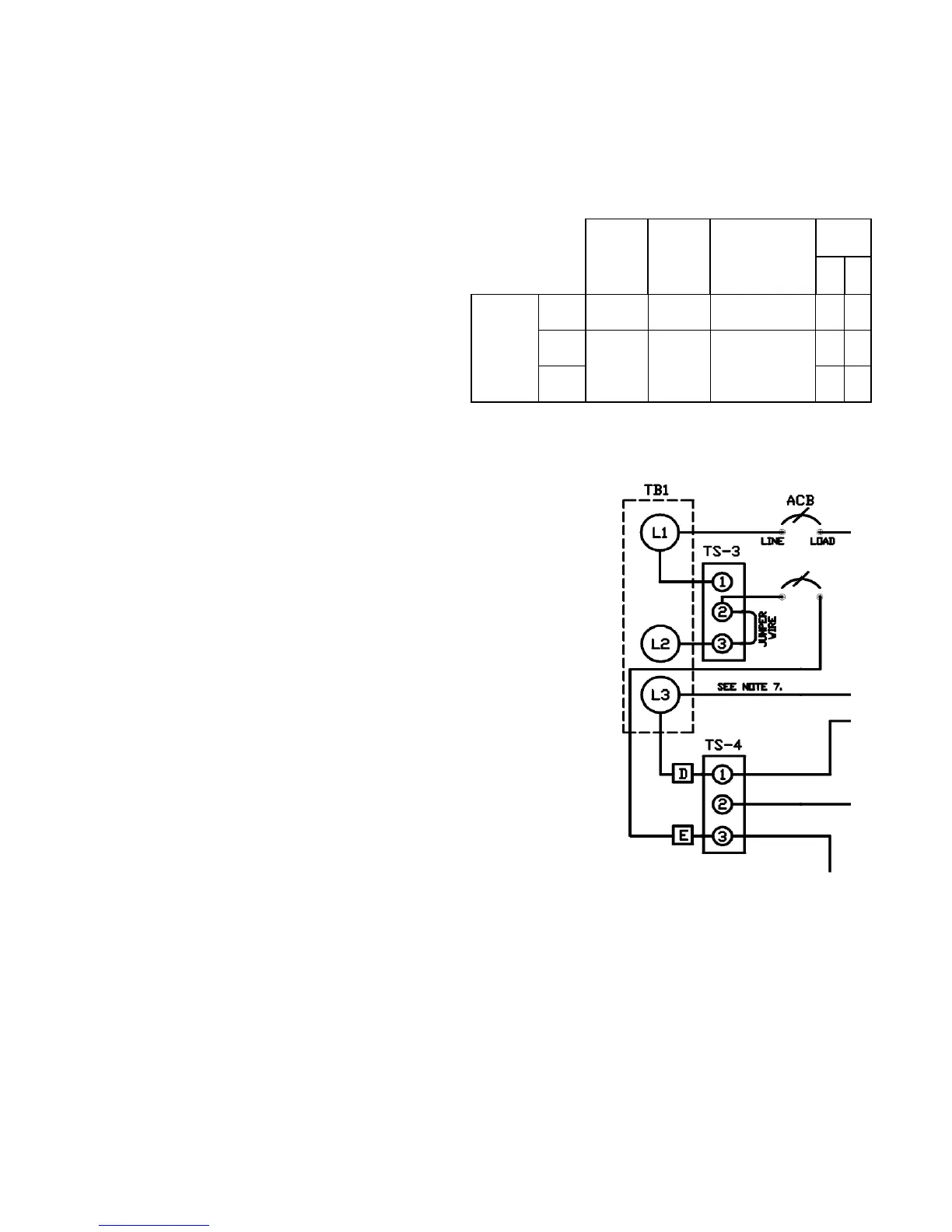
ACin1 ACin2
TS-3
Jumper
Connection
TS-4
DE
INPUT
VAC
120 L1 L3 1-2 3
1
208
L1 L2 2-3
2
3
240 1
3
Figure 8 - Input Terminals Connection
(Schematic – 240VAC input shown)
-
Input Terminal Connections