20
3.2 Digital Control Board
The TPSD is available with an LCD or VFD digital control board as Options 550 or 551 respectively. These
options replace the LED analog control board that is standard to the TPSD. The digital control board is a more
attractive and user friendly option, with many additional features over the standard LED analog control board.
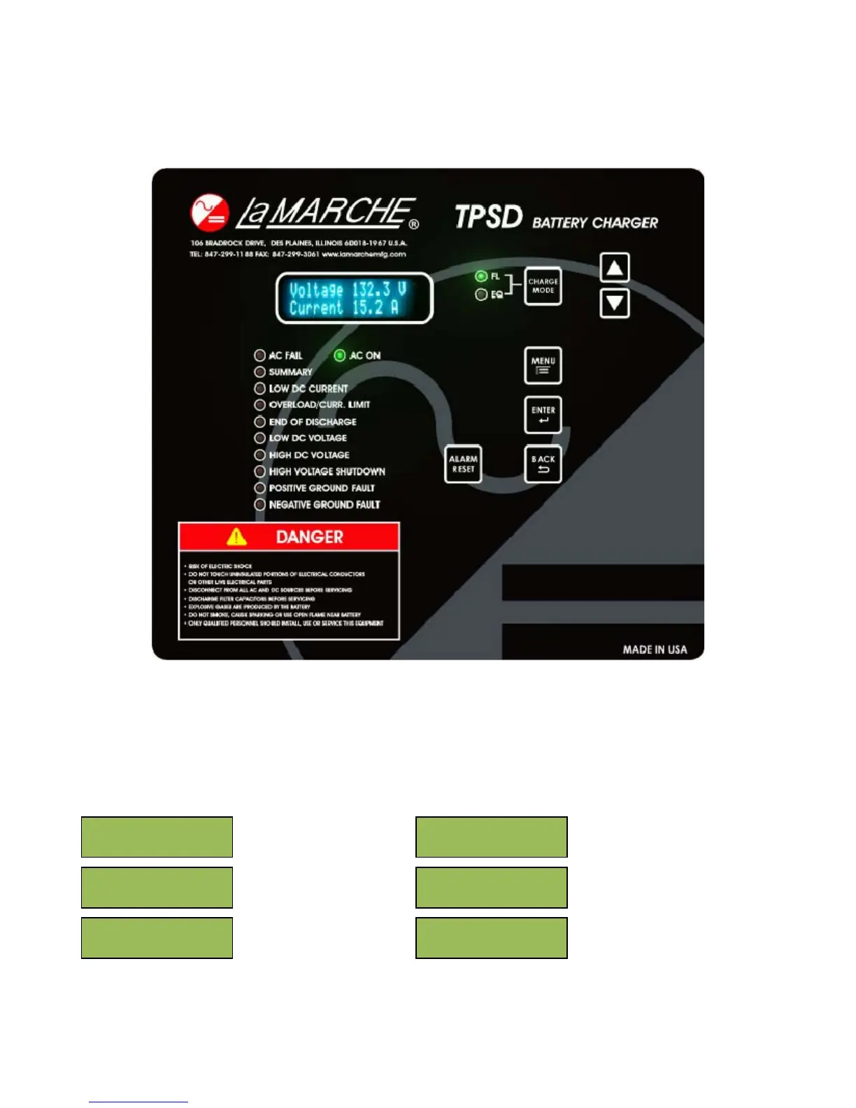
Figure 15 - TPSD Front Panel
After the TPSD has completed the startup sequence, “AC ON” and “FL” green LED indicators on the front panel
will be lit, additional indicators will be lit according to the system’s status. The digital meter display will show
both the system DC output voltage and DC output current. Pressing either the UP or the DOWN arrow on the
membrane will change the parameter that is displayed.
The parameters that can be displayed are as follows:
System DC Outputs
Temperature at Probe
(internal/external – based
on connection)
Temperature
Compensation Status
Equalize Timer Status and
Length
Time until next automatic
Equalize cycle
Selected Equalize Timer
Mode
oltage 132.3
Current 15.2 A
Temperature
Probe 27C
Temperature
Compensation OFF
EQ Timer OFF
8 Hour EQ
Next Auto EQ in:
OFF
EQ Timer Mode
Auto EQ OFF