Endurance
Page 13
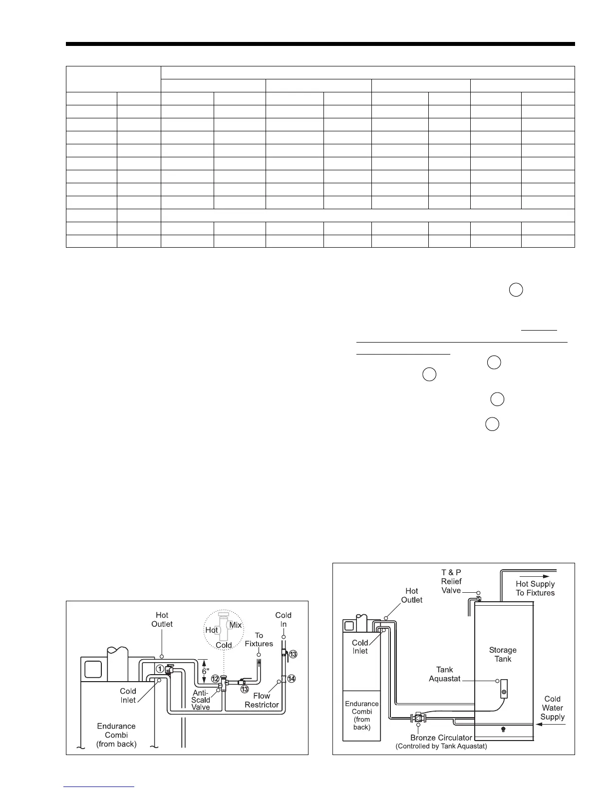
3.2 Domestic Water Piping (EBP only)
1. Connect tempering (mixing) valve 12 “Hot” port
to hot water outlet from unit. This valve should
be rated no higher than 120°F mixed delivery
temperature or as local codes dictate.
LAARS
RECOMMENDS ANTI-SCALD TEMPERING
(MIXING) VALVES (see Figure 16).
2. Connect gate or shutoff valve 13 to tempering
(mixing) valve 12 “MIX” port, and cold
water inlet.
3. Install supplied flow restrictor 14 ahead of
tempering (mixing) valve tee.
4. Connect pressure relief valve 1 (if required by
codes), rated at maximum 150 PSI as close to the
unit as possible. No other valves or restrictions
may be installed between the Endurance and the
relief valve.
DO NOT USE A TEMPERATURE/PRESSURE
RELIEF VALVE AS THIS IS NOT A STORAGE
HOT WATER HEATER.
NOTE: Installations with water containing 10 or
more grains of hardness, must be installed with
appropriate water treatment.
(3.2kPa). Check with your local gas utility or supplier
for availability of this pressure range.
Refer to Table 3 to size the supply piping to
minimize pressure drop between meter or regulator
and unit.
1. Run gas supply line in accordance with all
applicable codes.
2. Locate and install manual shutoff valves in
accordance with state and local requirements.
3. Install drip leg, ground joint union and drip cap
to trap sediment and for test gauge access.
4. Support all piping with proper hangers.
5. All threaded joints should be coated with piping
compound resistant to the action of liquefied
petroleum gas.
6. The boiler and its individual shutoff valve must
be disconnected from the gas supply piping
system during any pressure testing of that system
at test pressures in excess of ½ psig (3.5kPa).
7. The boiler must be isolated from the gas supply
piping system by closing its individual manual
shutoff valve during any pressure testing of the
gas supply piping system at test pressures equal
to or less than ½ psig (3.5kPa)
8. The boiler and its gas connection must be leak
tested before placing the boiler in operation.
9. Purge all air from gas lines.
Figure 16. Domestic Water Piping. Figure 17. Domestic Water Piping With Storage Tank.
Table 3. Gas Pipe Sizing.
Length Capacity of Pipe
of Pipe 1/2" 3/4" 1" 1-1/4"
ft. m MBTU/h kW MBTU/h kW MBTU/h kW MBTU/h kW
10 3 132 38.7 278 81.5 520 152.4 1050 307.7
20 6.1 92 27 190 55.7 350 102.6 730 213.9
30 9.1 73 21.4 152 44.5 285 83.5 590 172.9
40 12.2 63 18.5 130 38.1 245 71.8 500 146.5
50 15.2 115 33.7 215 63 440 128.9
75 22.9 93 27.2 175 51.3 360 105.5
100 30.5 79 23.1 150 44 305 89.4
150 45.7 64 18.8 120 35.2 250 73.3
Additional length to be added for each tee or elbow
ft m ft m ft m ft m
1.3 0.4 1.7 0.5 2.2 0.7 2.7 0.8