EasyManua.ls Logo

Laars NTV1000 - User Manual

Laars NTV1000
140 pages
Print Icon
To Next Page IconTo Next Page
Loading...
Installation and Operation Instructions Document 1255B
H2352900B
WARNING
If the information in this manual is not
followed exactly, a re or explosion may
result causing property damage, personal
injury or loss of life.
Do not store or use gasoline or other
ammable vapors and liquids in the vicinity
of this or any other appliance.
WHAT TO DO IF YOU SMELL GAS
Do not try to light any appliance.
Do not touch any electrical switch; do not
use any phone in your building.
Immediately call your gas supplier from a
nearby phone. Follow the gas supplier’s
instructions.
If you cannot reach your gas supplier, call
the re department.
Installation and service must be performed
by a qualied installer, service agency, or gas
supplier.
FOR YOUR SAFETY: This product must be installed and serviced by a professional service technician,
qualied in hot water boiler and heater installation and maintenance. Improper installation and/or operation
could create carbon monoxide gas in ue gases which could cause serious injury, property damage, or
death. Improper installation and/or operation will void the warranty.
AVERTISSEMENT
Assurez-vous de bien suivres les instructions
données dans cette notice pour réduire au
minimum le risque d’incendie ou d’explosion ou
pour éviter tout dommage matériel, toute blessure
ou la mort.
Ne pas entreposer ni utiliser d’essence ni d’autres
vapeurs ou liquides inammables dans le
voisinage de cet appareil ou de tout autre appareil.
QUE FAIRE SI VOUS SENTEZ UNE ODEUR DE GAZ:
Ne pas tenter d’allumer d’appareils.
Ne touchez à aucun interrupteur. Ne pas vous
servir des téléphones dansle bâtiment où vous
vous trouvez.
Appelez immédiatement votre fournisseur de
gaz depuis un voisin. Suivez les instructions du
fournisseur.
Si vous ne pouvez rejoindre le fournisseur de
gaz, appelez le sservice des incendies.
L’installation et l’entretien doivent être assurés par
un installateur ou un service d’entretien qualié ou
par le fournisseur de gaz.
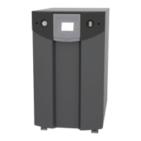
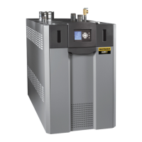
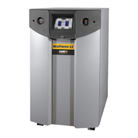
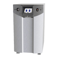
Installation and
Operation Instructions for
NEOTHERM
®
LC
Modulating Boiler Water Heater
Model NTH1000 Model NTV1000
1,000 MBTU/h 1,000 MBTU/h
Model NTH1700 Model NTV1700
1,700 MBTU/h 1,700 MBTU/h

Table of Contents

Other manuals for Laars NTV1000

Questions and Answers

Summary

Installation and Operation Overview

NEOTHERM LC Product Introduction

Introduces the NEOTHERM LC boiler and water heater models.

Essential Safety Precautions

Highlights critical safety warnings for installation and operation to prevent hazards.

General Information

Introduction to NeoTherm LC Systems

Provides an overview of the manual and system.

Touch Screen Display Functionality

Explains how to navigate and use the touch screen interface.

Safety Notes and Hazards

Details fire, explosion, CO, and electrical shock hazards.

Model Identification and Warranty

Explains model nomenclature and warranty coverage.

Appliance Overview and Dimensions

Provides a visual overview of unit components and key dimensions.

Unpacking Instructions

Guides on how to unpack the unit and check included parts.

Venting and Combustion Air Requirements

Combustion Air Supply and Ventilation

Details requirements for providing combustion and ventilation air.

Venting System Requirements

Outlines Vent Category IV requirements and material specifications.

Locating Vent and Combustion Air Terminals

Specifies placement guidelines for vent and air intake terminals.

Condensate Drain Trap Installation

Explains the installation and requirements for the condensate drain trap.

Gas Supply and Piping

Gas Supply and Piping Installation

Provides instructions and code references for gas supply and piping.

Water Connections

NTH System Piping and Connections

Covers piping requirements for hydronic heating (NTH) systems.

NTV System Water Quality and Piping

Details water quality and piping for domestic hot water (NTV) systems.

Electrical Connections

Main Power and Pump Connections

Explains power supply and pump connection procedures.

Signal and Optional Field Connections

Covers signal wiring and optional component connections.

Ladder and Wiring Diagrams

Provides schematics for electrical connections and system logic.

Using the Touch Screen and Gauges

Touch Screen Interface Overview

Introduces the touch screen interface for system control and monitoring.

Navigating Lead;Lag System Functions

Guides on checking operating status and parameters in Lead/Lag systems.

Checking Individual Controller Parameters

Explains how to view and verify settings for individual controllers.

Verification Process for Safety Parameters

Details the procedure for verifying safety-related parameter changes.

Setup and Configuration

Lead;Lag Control System Overview

Explains the concept and operation of the Lead/Lag control system.

Lead;Lag Modulation Cycle Details

Describes how burners modulate based on heating demand.

Domestic Hot Water Setup Types

Outlines different methods for configuring DHW in a Lead/Lag system.

Gateway Connections and High Altitude Setup

Covers connecting to automation systems and NT 1700 high altitude adjustments.

Installer Parameter Configuration

Lists and explains parameters configurable by installers.

Initial Startup Instructions

Filling the Boiler System

Step-by-step guide for filling the system with water and bleeding air.

Initial Operation and Setup

Covers initial burner firing, safety checks, and combustion setup.

Shutting Down the NeoTherm LC

Procedure for safely turning off the boiler system.

Restarting the NeoTherm LC

Instructions for bringing the boiler back online after shutdown.

Maintenance

System Maintenance Procedures

Details annual and semi-annual maintenance tasks for the system.

Component Maintenance and Troubleshooting

Covers maintenance for specific components like burners, valves, and sensors.

Gas Conversion and Battery Replacement

Explains gas conversion procedures and touchscreen battery replacement.

Troubleshooting

Potential Setup and Synchronization Issues

Addresses common problems with controller synchronization and flap valve status.

Understanding Lockouts, Holds, and Alerts

Explains different types of system fault indications and their meanings.

Troubleshooting Tables and Error Codes

Provides a comprehensive list of faults, codes, and corrective actions.

Diagnostic Tests and Input;Output Indicators

Details how to use diagnostic screens to check system inputs and outputs.

Lead;Lag System Analysis and History

Covers analyzing system behavior and viewing lockout/alert logs.

Replacement Parts

General Information on Parts Ordering

Provides guidance on how to order genuine LAARS replacement parts.

Parts List and Illustrations

Lists part numbers and provides visual diagrams for component identification.

Parts Illustrations

Machine Frame Diagrams

Visual representations of the machine frame for NT1000 and NT1700.

Rear Panel Diagrams

Exploded views of the rear panels for NT1000 and NT1700.

Burner and Combustion Chamber Diagrams

Illustrations showing the burner and combustion chamber assemblies.

Heat Exchanger and Component Views

Diagrams detailing heat exchanger components and burner assembly.

Electronic Components and Traps

Illustrations of electronic components, condensate traps, and flow switches.

Laars NTV1000 Specifications

General IconGeneral
BrandLaars
ModelNTV1000
CategoryBoiler
LanguageEnglish

Related product manuals