NeoTherm LC Boilers and Water Heaters
Page 41
3. Press the Congure button to start a
conguration session for the selected
controller. See Fig. 39.
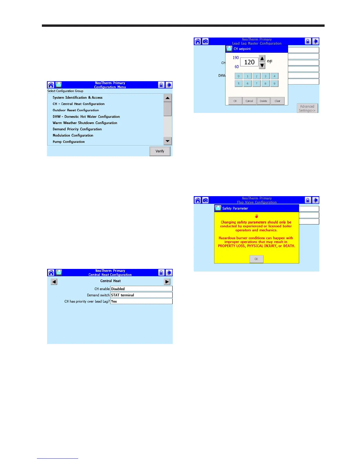
Fig.39-CongurationScreen
This screen lists all of the conguration
groups. (The list is actually longer – scroll
down using the bar on the right side of the
screen.) Many of the items will not be useful
to an installer or end-user.
4. Next, we will show you how to change one
of these parameters. Let’s turn on the Central
Heat function. On the Conguration Screen
(Fig. 39), scroll down and press the line for
CH – Central Heat Conguration. Figure 40
shows the screen which follows.
Fig.40-CentralHeatConguration
On the screen, you can see the Central Heat
function is currently disabled. To turn on the
Central Heat function, press the space beside
CH Enable. The system will tell you that you
must login and enter a password to change this
entry.
5. The process would be the same if you wanted
to change a numerical value, except that
system would present a numeric entry screen.
See Fig. 41.
Fig. 41 - Numeric Entry Screen
8.8 VericationProcessforSafety-
Related Parameters
1. When you start to change a parameter that
is related to safety, the system will present a
warning which looks like this:
Fig. 42 - Parameter Safety Warning
Press OK to continue. The system will ask
you to login before you make a change. (For
more information on logging in, see Section
8.2.)
Note that any changes you make will apply
only to one controller – the controller you
have already selected. If you want the same
change to apply to other controllers, you must
change each of them separately.
2. If you make a change in any group that could
affect the safe operation of the unit, the control
system will ask you to “verify” the change
before it is accepted. As an example, let’s say
that we wanted to change the conguration
for one of the ap valves. See Fig. 43. A
line printed in red at the bottom of the screen
indicates that the system wants to do a safety
verication. (All of the parameters in this
group have safety-related functions. If you
change any of them, you will have to do the
verication for the whole group.)
 Loading...