NeoTherm LC Boilers and Water Heaters
Page 59
Primary Control on Boiler 1 is “1.” If this
is not already set to “1”, enter the correct
number, then press OK.
WARNING
If the addresses are not assigned properly, the
system could fail to operate correctly, or it might
operate in an unsafe manner. This could lead to
property damage, personal injury or death.
10. Now you can use the same process to set the
address for the Secondary control for Boiler 1.
On the Control Setup screen (Fig. 65), press
the second line – NeoTherm LC Secondary.
Change the address to the correct address
taken from Table 3. In this case, the correct
address would be “2.”
11. Go to the Touch Screen for Boiler 2. Repeat
the process to change the addresses for
Boiler 2 Primary (address = 3) and Boiler 2
Secondary (address = 4).
12. Repeat steps 3 - 10 for each of the other
controllers connected to the system.
Job F - Set the Flap Valve IDs
(These are individual functions. Make the ap valve assignment
on each of the controllers. Use the Touch Screen on each of the
boilers.)
Do this on any system with multiple boilers.
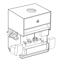
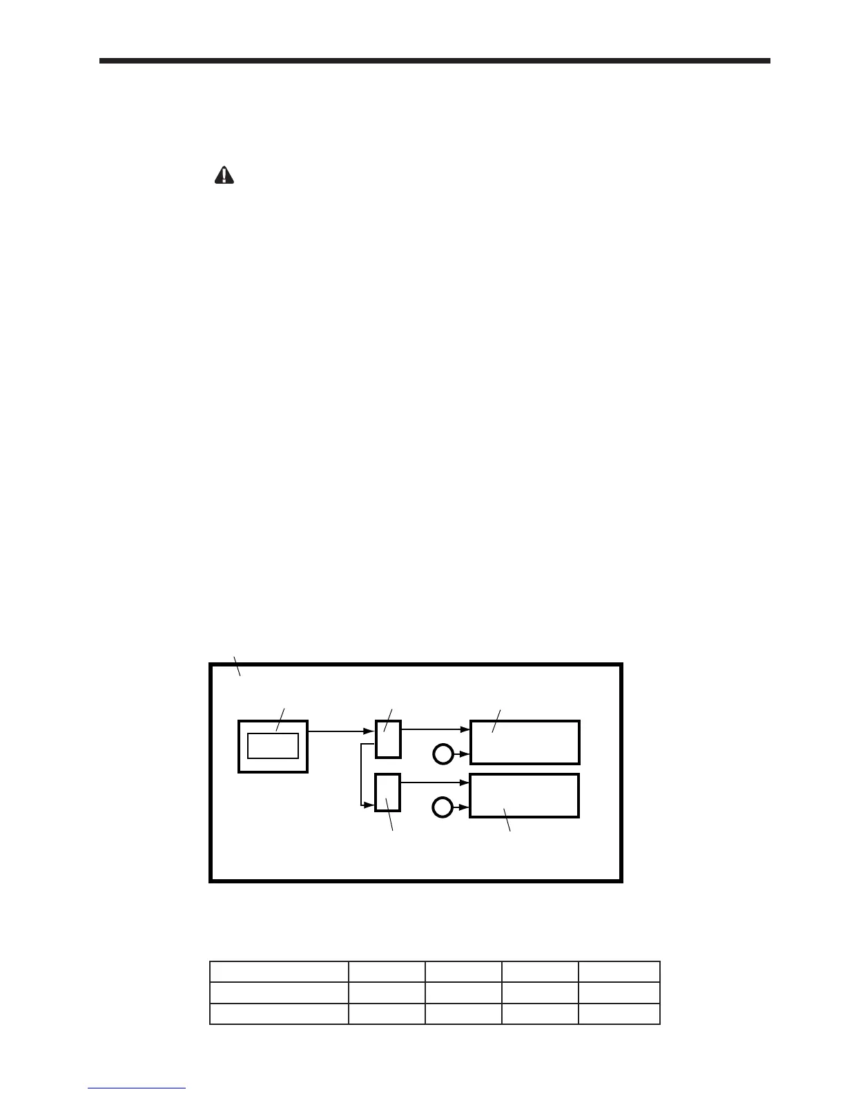
Each boiler includes two burners, and each burner
has a ap valve. See Fig. 67.
A ap valve acts like a one-way valve or check
valve. If one burner in a boiler is operating, and
the other is not, one of the ap valves will close to
prevent exhaust air from moving backwards through
the burner that is not operating.
Before the Lead/Lag Master controller will allow
the system to operate, it must be able to determine
whether each of these ap valves is open or closed.
If the controller cannot nd a signal from one of the
ap valves, the control system will act to prevent
backow by energizing the blower of the control
with the bad ap valve. (The positive pressure from
the blower will prevent the exhaust air from moving
back through the burner.) If this cannot be done, the
Lead/Lag Master controller will not allow the whole
system to run. For this reason, it is important that all
of the ap valves be identied correctly.
Each controller in the system needs to know how
many controllers are included in the whole system.
You will need to enter this information in each of the
controllers separately.
Boiler 1 Boiler 2 Boiler 3 Boiler 4
Primary control 1 3 5 7
Secondary control 2 4 6 8
Table 13 – Modbus Control Addressing
Primary
burner
Primary
controller
Flap
valve
Flap
valve
Secondary
controller
Secondary
burner
Operator
interface
Boiler 1
Fig. 67 - Flap Valve Arrangement
 Loading...