Page 38
LAARS Heating Systems
SECTION 12.
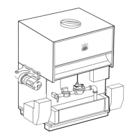
Parts Identification
Item # Description EBP0110 EBP0175 EDP0110 EDP0175 EDN0110 EDN0175
1. Pan, Combustion Chamber, Top 2400-502 2400-502 2400-449 2400-449 2400-449 2400-449
2. Pan, Combustion Chamber, Bottom 2400-504 2400-504 2400-504 2400-504 2400-504 2400-504
3. Insulation, Coil Cover 2400-506 2400-506 2400-506 2400-506 2400-506 2400-506
4. Insulation, Boiler Coil 2400-508 2400-508 2400-508 2400-508 2400-508 2400-508
5. Coil, Boiler 2400-510 2400-512 2400-510 2400-512 2400-510 2400-512
6. Gasket, Burner 2400-514 2400-514 2400-514 2400-514 2400-514 2400-514
7. Burner 2400-516 2400-518 2400-516 2400-518 2400-516 2400-518
8. Transfer Tank 2400-586 2400-586 ————
9. Boiler Drain 2400-522 2400-522 2400-522 2400-522 2400-522 2400-522
10. Blower, Combustion Air (with gasket) 2400-524 2400-524 2400-524 2400-524 2400-524 2400-524
11. Gasket, Blower 2400-540 2400-540 2400-540 2400-540 2400-540 2400-540
12. Ignitor / Flame Sensor (with gasket) 2400-526 2400-526 2400-526 2400-526 2400-526 2400-526
13. Gasket, Ignitor / Flame Sensor 2400-528 2400-528 2400-528 2400-528 2400-528 2400-528
14. Combustion Air Inlet 2400-142 2400-142 2400-142 2400-142 2400-142 2400-142
15. Coin Vent 2400-530 2400-530 2400-530 2400-530 2400-530 2400-530
16. Anti-Condensing Valve Repair Kit 2400-538 2400-538 ————
16. Anti-Condensing Valve, Operator Only 2400-539 2400-539 ————
17. Water Flow Switch 2400-542 2400-542 ————
18. Safety Limit, 230°F 2400-550 2400-550 2400-550 2400-550 2400-550 2400-550
19. Sensor, Tank 2400-445 2400-445 ————
20. Sensor, Supply 2400-445 2400-445 2400-445 2400-445 2400-445 2400-445
21. Sensor, Return 2400-446 2400-446 2400-446 2400-446 2400-446 2400-446
22. Thermostatic Union (not shown) — — 2400-030 2400-030 2400-447 2400-447
23. Pump 2400-592 2400-386 2400-592 2400-386 2400-388 2400-388
24. Gaskets, Pump Flange 2400-566 2400-566 2400-566 2400-566 2400-566 2400-566
25. Gas Valve 2400-548 2400-548 2400-548 2400-548 2400-548 2400-548
26. Gas Shutoff Valve 2400-560 2400-560 2400-560 2400-560 2400-560 2400-560
27. Heat Exchanger, DHW 2400-570 2400-570 ————
28. Gaskets, DHW Heat Exchanger 2400-572 2400-572 ————
29. Boiler Control 2400-439 2400-439 2400-440 2400-440 2400-440 2400-440
30. Ignition Control 2400-441 2400-441 2400-441 2400-441 2400-441 2400-441
31. Reset Switch 2400-568 2400-568 2400-568 2400-568 2400-568 2400-568
32. PWM Board 2400-442 2400-442 2400-442 2400-442 2400-442 2400-442
33. Transformer 2400-448 2400-448 2400-448 2400-448 2400-448 2400-448
34. Relay — — R2006100 R2006100 R2006100 R2006100
35. Wiring Harness (not shown) 2400-443 2400-443 2400-444 2400-444 2400-444 2400-444
36. Gauge, Pressure (not shown) 2400-574 2400-574 2400-574 2400-574 2400-574 2400-574
37. Pressure Relief Valve (not shown) 2400-112 2400-112 2400-112 2400-112 2400-112 2400-112