Home
Laars
Boiler
NTV1000
Page 47
Laars NTV1000 - Page 47
140 pages
Manual
Save Page as PDF
To Next Page
To Next Page
To Previous Page
To Previous Page
Loading...
NeoTherm LC Boilers and W
ater Heaters
Page 43
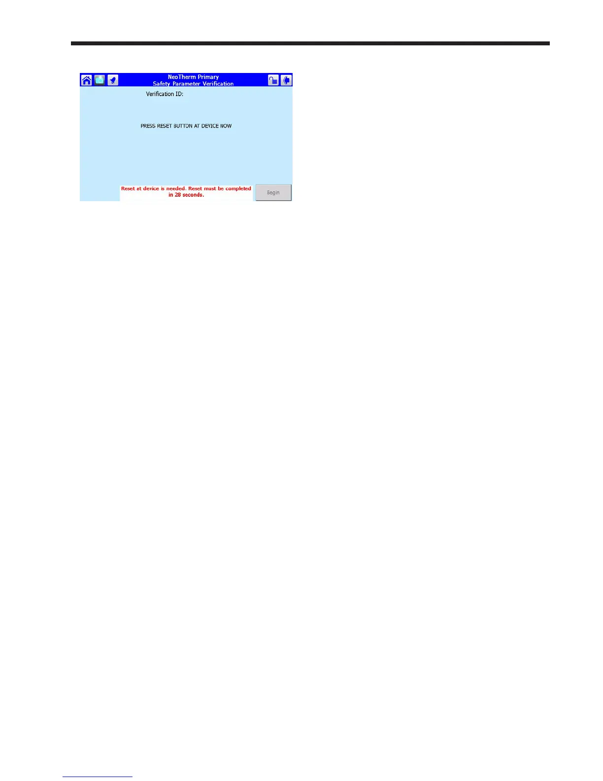
Fig. 47 - Safety Parameter Reset
7.
The Reset button is located on the front of
the controller
. See Fig. 44.
Y
ou must press
the Reset button within 30 seconds, or the
verication will be cancelled.
46
48
Table of Contents
Main Page
Table of Contents
2
General Information
5
Introduction
5
Section
5
About the Touch Screen
5
Safety Notes
7
Model Identification / Nomenclature
7
Warranty
8
Appliance Overview
8
Dimensions
10
Unpacking
10
Section
12
Locating the Appliance
12
Correct Vent Distance from Outside Wall or Roof Termination
12
Venting and Combustion Air
13
Combustion Air
13
Combustion Air From Room
13
Ducted Combustion Air
14
Venting
15
Common Venting
15
Venting Requirements Unique To Canada
15
Locating the Vent and Combustion Air Terminals
16
Side Wall Vent Terminal
16
Side Wall Combustion Air Terminal
18
Vertical Vent Terminal
19
Vertical Combustion Air Terminal
19
Installations in the Commonwealth of Massachusetts
19
Common Vent Test
19
Outdoor Installation
20
Condensate Trap
20
Section
21
Distance & Pipe Size, Tables
22
Pump Requirements
23
Gas Supply and Piping
21
Neotherm LC Boiler Flow and Head Requirements
23
Neotherm LC Water Heater Flow and ...... Head Requirements ................................ 19
23
Water Connections
24
Section 6A - Nth Systems
24
NTH System Piping: Hot Supply Connections
24
Nth Cold Water Make-Up
24
Nth Freeze Protection
25
Nth Suggested Piping Schematics
25
Condensate Trap
25
Section 6B - Ntv Systems
31
Ntv Water Quality
31
Ntv Piping Requirements
31
Ntv Cold Water Make-Up
32
Ntv Freeze Protection
32
Ntv Suggested Piping Schematics
32
Ntv Suggested Pumps
33
Condensate Trap
33
Electrical Connections
34
Section
34
Main Power
34
Pump Connections
34
VAC Transformer with Integral Circuit Breaker
36
Signal Connections
36
Optional Field Connections
36
Wiring Diagrams
36
Ladder Diagrams
37
Using the Touch Screen and Gauges
40
The Touch Screen and Gauges on the Front of the Neotherm LC
40
Using the Touch Screen
40
While Operating - Checking Lead/Lag Operating Information
42
Checking Lead/Lag Master
42
While Operating - Checking Individual Parameters
43
Checking Individual Details
44
Configuring Parameters on Individual Controllers
44
Verification Process for Safety-Related Parameters
45
Setup and Configuration
48
Review of Lead/Lag Control System
48
About Lead/Lag Operation
48
Lead/Lag Modulation Cycle
49
NTH Lead/Lag with Indirect Domestic Hot Water
50
Connection Terminals
50
Neotherm LC System Configurations
50
A Note For Systems Using Common Venting
59
C Make One Control The Lead/Lag Master
60
Master
60
D Disable the Lead/Lag Master Function on the Lead/Lag Slaves
61
Set up the Modbus Control Addressing
62
Set the Flap Valve Ids
63
G Disconnect Unused Operator Interfaces
67
H Connect the Modbus Wiring
67
Lead/Lag System
68
About The "Time Of Day" Function
72
J Install the System Sensor and Adjust the Setpoint
72
Warm Weather Shutdown
72
About Outdoor Reset
73
L Building Automation or Multiple Boiler Control Thermostat Demand
74
M Building Automation or Multiple Boiler 4-20Ma Setpoint Control
74
N Building Automation or Multiple Boiler 4-20Ma Modulation Control
75
O Combustion Setup Procedure
75
System Display
80
Installation Jobs
59
Venting
59
B Naming the Controllers
59
Setup for Domestic Hot Water on a Lead/Lag System
81
Setup Type 1
81
Setup Type 2
82
Setup Type 3
83
Gateway Connections to a Building Automation System
84
Setup for High Altitude Operation - Nt 1700 Only
84
Installer Parameters
85
Initial Startup Instructions
92
Filling the Boiler System
92
Initial Operation
93
Initial Burner Operation
93
Combustion Setup Procedure
93
Shutting down the Neotherm LC
93
Restarting the Neotherm LC
93
Maintenance
94
System Maintenance
94
Maintenance Notes
94
Burner
94
Modulating Gas Valve/ Venturi
94
Controllers
95
Ignitor Assembly
95
Flame Sensor
95
Transformer with Integral Circuit Breaker
95
Blower
96
Heat Exchanger Coils
96
Gas Pressure Switches (Optional)
96
Natural/Propane Gas Conversion
97
Condensate Trap
97
Battery (Date & Time Back-Up)
97
Troubleshooting
98
Potential Setup and Synchronization Problems
98
Controller Synchronization
98
Flap Valve Status Checks
99
About Lockouts, Holds, and Alerts
99
Responding to a Lockout, Hold, or Alert
99
Viewing the Lockout and Alert Histories
100
Troubleshooting Tables (All Codes)
102
Diagnostic Tests and Input/Output Indicators
117
Lead/Lag Slave Diagnostics
118
Statistics
118
Analysis
118
Control Snapshot
119
Operating Sequence
119
Replacement Parts
122
General Information
122
Parts List
122
Parts Illustrations
128
Other manuals for Laars NTV1000
User Manual
12 pages
Related product manuals
Laars NTH1000
140 pages
Laars NEOTHERM LC
140 pages
Laars newport NP 75
11 pages
Laars newport NP 85
11 pages
Laars newport NP 135
11 pages
Laars newport NP 100
11 pages
Laars FT Series
100 pages
Laars MASCOT LX
56 pages
Laars Mighty Therm
36 pages
Laars MASCOT FT MFTCW
80 pages
Laars mascot ft MFTHW
96 pages
Laars Mighty Therm HH 500
28 pages
 Loading...