NeoTherm LC Boilers and Water Heaters
Page 61
Table 14 – Number of Controls
Number of
boilers
Number of
controls
2 4
3 6
4 8
For example, if your system has three boilers,
there would be a total of six controllers (two
for each boiler), so you would enter “6” for
Number of Controls.
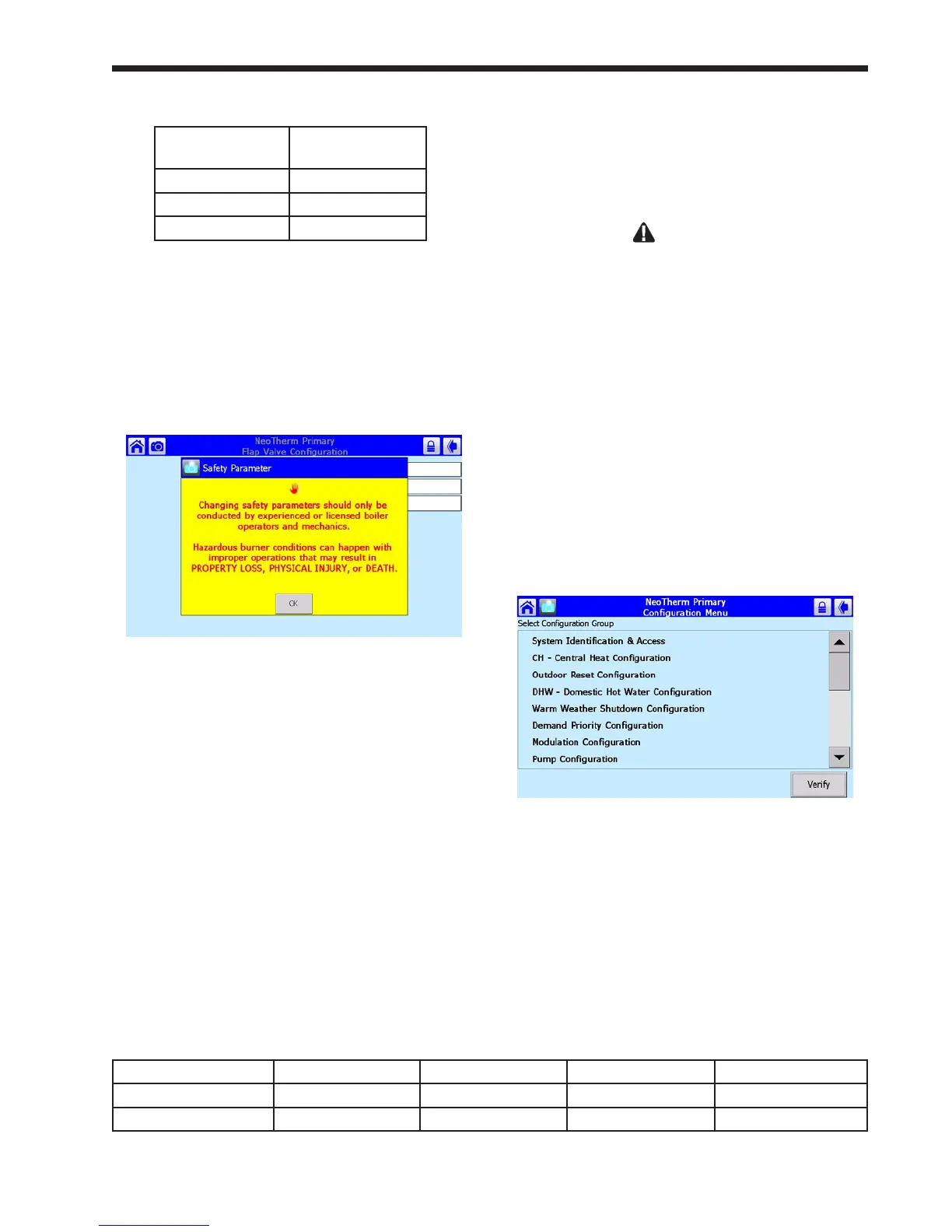
5. Press the line for Controller ID. Because you
are changing a parameter that is related to
safety, the system will present a warning that
looks like this:
Fig. 72 – Parameter Safety Warning
Press OK to continue. The system will ask
you to login before you make a change.
Note that any changes you make will apply
only to one controller – the controller you
have already selected. If you want the same
change to apply to other controllers, you must
change each of them separately.
Once you change one of these safety-related
parameters, you must nish the verication
process, or the control system will not let the
boiler operate. Each control in a boiler must
be veried separately.
6. Press again on the line for Controller
ID. Table 15 shows how the Primary and
Secondary controls should be numbered for
each of the boilers.
In this example, we are still working with the
Primary control for Boiler 1. From the table,
you can see that this control should have a ap
valve ID of “1.” Enter the correct ID from
Table 5 in this eld.
WARNING
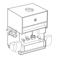
If the controller cannot nd a signal from one
of the ap valves, the control system will act to
prevent backow by energizing the blower of the
control with the bad ap valve. If this cannot be
done the control will not allow the whole system to
run. For this reason, it is important that all of the
ap valves be identied correctly.
7. Set the address for the other controller on this
boiler in the same way.
8. At this point, you have set the ap valve ID’s
for both controllers on this boiler. Before you
leave, you must nish the verication process,
or the control system will not let the boiler
operate.
Press the Back arrow to return to the
Conguration screen.
Fig.73–CongurationScreen
9. In a moment, you will need to reset the
controller by pressing a button on the front of
the unit. See Fig. 74. The controllers for the
two boilers are mounted behind the door on
the front of the unit.
Boiler 1 Boiler 2 Boiler 3 Boiler 4
Primary control 1 3 5 7
Secondary control 2 4 6 8
Table 15 – Flap Valve Controller ID Addressing
 Loading...